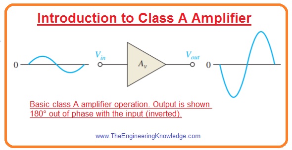
 Hello friends, I hope you all are doing great. In today’s tutorial, we will have a look at Introduction to Class A Amplifier. The class A amplifier gives large with higher linearity. The conduction angle for this amplifier is three-sixty degrees which means the output transistor continues its operation for the complete input waveform. Due to continuous operation, this module gives high frequency and feedback loop stability. Its construction is also very easy.
Due to continuous operation, there is high power loss occurs for this amplifier with that signal distortion and noise also generated. Due to large power loss, it generates heat to reduce it heat sink is required. Due to power loss, it gives less efficiency almost twenty-five to thirty-five percent. In today’s post, we will have a detailed look at its working, circuit configuration and some related parameters. So let’s get started with Introduction to Class A Amplifier.
Introduction to Class A Amplifier
- The amplifier which amplifies small signals the ac signal moves for less quantity over the total ac load line.
- If the output of the amplifier is large and almost equals to the ac load line this amplifier is known as large-signal amplifier.
- Both amplifiers either it is large or small will know as class A amplifier if they are operating in the linear region all the time as shown in the below figure.
- The large signal amplifiers are known as class A amplifier which provides power to load instead of voltage.
- Any amplifier is called class amplifier if its rating is larger than the one watt and it generates heat in the circuitry.
Heat Dissipation
- Power transistors should dissipate a huge volume of internally produced heat.
- In the case of bipolar junction transistor, the collector is a critical junction due to this casing of transistor is always attached to the collector.
- The casing of all power transistors is created to deliver a large connection area among transistors and exterior hear sink.
- The heat generated flows to the sink from transistor casing and then moves to the surrounding area.
- The heat sink has variable size, the different number of fins and material used for construction.
- The size of these sink depend on the heat dissipation and maximum ambient temperature over which the transistor is operated.
- In large amplifier applications usually some hundred watts a cooling fan can also be used.
Centered Q-Point
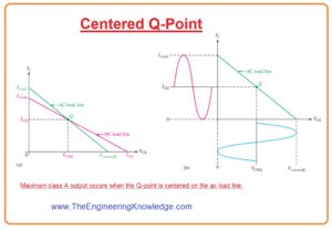
- As we know that dc and ac load lines intersect at Q-point. If the Q point is at the midpoint of ac load line the maximum class a signal can get.
- We can observe this process by analyzing the grapgh of load line as shown in figure denoted as (a).
- In this graph is showing ac load line with Q point at its midpoint.
- The collector current can change from its Q point value ICQ to its saturation point and down to its cutoff value of 0.
- Similarly, the collector to emitter voltage can swipe from its Q-point value VCEQ to its cutoff value, Vce(cutoff ), and down to its saturation value of almost 0.
- This process is shown in figure denoted as (b).
- The peak value of collector current equal to the ICQ and peak (maximum) value of collector to emitter voltage equal to the VCEQ.
- This signal is highest which can get from the class A amplifier.
- In fact, the output cannot relatively reach saturation or cutoff, so the practical extreme is to some extent less.
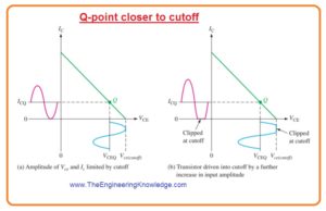
- If Q point is not at midpoint od ac load line the output signal will be limited.
- In the below figure you can see that ac load line away from Q-point near to the cutoff.
- In this condition output variation is restricted by the cutoff.
- The collector current can only move toward 0 and equal quantity over ICQ.
- The VCE can only swing to their cutoff value and an equal amount below VCEQ.
- This situation is shown in figure denoted as (a).
- If an amplifier is further driven from this point it will clip at a cutoff point as denoted (b) in the figure.
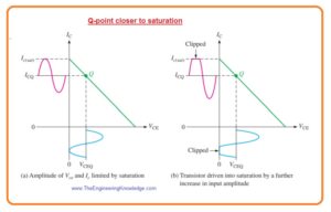
- In below figure ac load line is drawn with Q point moved toward saturation point from midpoint of load line.
- In this condition output changes is restricted by the saturation.
- The collector current only moves to near saturation and the same quantity below ICQ.
- The VCE can only swing down to its saturation point and same amount above VCEQ.
- It is explained in figure denoted as (a).
- If amplifier is running any further it will clip at saturation point shown in figure denoted as b.
Class A Amplifier Power Gain
- The power gain of an amplifier is ratio among the output power that is delivered to load to input power.
Ap=PL/Pin—–(A)
- In this equation, Ap is power gain PL is signal power given to the load and Pin is signal power providing to the amplifier.
- There are numerous formulas can be used to find power gain according to knonw values.
- Usually, the easy method to find the power gain is from input resistance value, load resistance, and from voltage gain.
- To see how it work we use a known formula for power.
P=V2/R
- In the case of ac power voltage can be defined as rms or root mean square value.
- The output power given to load is.
PL=V2L/RL
- Input power given to the load is
Pin=V2in/c
- By putting in equation A we have.
Ap=V2L/V2in(Rin/RL)
As VL/Vin = Av
Ap=A2v(Rin/RL)—-(b)
- Equation for voltage divider baised amplifier is given as.
Rin(tot) = R1ΙΙ R2 ΙΙRin(base)
- For CE amplifier.
Rin(base)=βacRe
- The equation b indicates that power gain of class A amplifier is the square of voltage gain times the ratio between input resistance to output resistance.
- This equation can be used for any amplifier. For instance, suppose that the input resistance of the common-collector amplifier is five-kilo ohm and load resistance is one hundred ohms.
- As the voltage gain of a common-collector amplifier is one the power gain will be.
Ap=A2v(Rin/RL)
=12(5kΩ/100Ω)=50
- For common collector amplifier power gain is ratio between input resistance to output load resistance.
Class A Amplifier DC Quiescent Power
- The power loss of transistors in the absence of an input signal is the product of its Q-point current and voltage.
PDQ= ICQVCEQ——-(c)
- The only method is for class A amplifier to deliver power to the load is to sustain a quiescent current which has a value equal to peak current for the load.
- The signal will not increase the power lost by the transistor but reduces the total power dissipation.
- the dc quiescent power shown in equation c is the maximum power which class A amplifier can withstand.
- The power rating of a transistor should be larger than this value.
Class A Amplifier Output Power
- In normal the output power is the product of RMS load current and rems load voltage.
- The extreme unclipped ac signal exits when the Q-point is at the midpoint of the ac load line.
- For common emitter amplifier with Q point at the center the extreme peak voltage swing is given as.
Vc(max) = ICQR
- The RMS value is 0.707Vc(max). The maximum peak current swing will be given as.
Ic(max)=VCEQ/Rc
- The rms value will be 0.707Ic(max).
- To determine the maximum signal power output we will use max rms value of current and voltage.
- The max power taken out from the amplifier will be given as.
Pout(max) = (0.707Ic)(0.707Vc)
Pout(max) =0.5ICQVCEQ—(d)
Class A Amplifier Efficiency
- The efficiency of any amplifier is the ratio of output signal given to the load to the power of the dc source.
- The maximum output power which can get is denoted in equation d.
- The average current of power supply ICC is equal to the ICQ and supply voltage at least 2VCEQ.
- So total dc power will be.
PDC = ICCVCC = 2ICQVCEQ
- The maximum efficiency of capacitively coupled class A amplifier will be given as.
ηmax=Pout/PDC
=0.5ICQVCEQ/2ICQVCEQ=0.25
- The max efficiency of capacitively coupled class A amplifier can’t be greater than twenty-five percent and in practice, it is normally less than ten percent.
- Though the efficiency can be made large with the use of transformer-coupled with the load, there is some disadvantages of transformer coupling.
- This disadvantage comprises of transfer large size and price and core related issues of a transformer.
- In normal less efficiency of class, A amplifier restricts the usefulness for small power applications which need normally less than one-watt power.
So, friends, it is detailed post about class A Amplifier if you have any questions ask in comments. Thanks for reading.




Hi. I’m glad he found theengineeringknowledge.com website, I really like it, the article is
very useful and I shared it!