 Flexible PCB is called FPC (Flexible Printed Circuit), a quickly growing technology that is used for different electronic projects like automobiles, electro-medical devices telecom sector, and the aviation industry. The use of flexible boards has innovated electrical interconnection methods and is used for connecting different electronic devices. These boards have replaced different types of wiring done by hand reducing the expenses for wiring by about 70 percent.
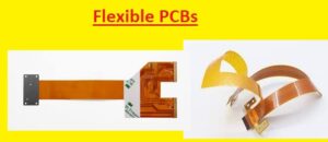
What are Flexible PCBs?
The flexible PCB board comes with a mixture of different PCBs also components that are configured on a flexible substrate. These boards are also called flexible boards, flex PCBs, and Flex circuits.
These boards are made with the use of components used for rigid PCBs. The basic difference is that the board is made with flexible material for the required structure.

Flexible PCB Benefits
- There are different advantages of this board explained here
Lightweight Package:
- Flexible boards can easily confined in projects where other boards are not easy to configure These boards are thin less weight and easily folded and configured in parts where other components do not fit.
Accurate Designs:
- Flex boards are made and designed with the use of automated machines. It helps to reduce duces faults that are caused in hand made wires and provides accuracy, that is according to the requirements of devices
East to Design:
- The design of a flexible board does not come with only two layers. They can easily desing in different types. They are made single-sided with a single access, single-sided with double access, and multilayer combination also with rigid and flexible circuits. Their flexible design makes them best for complicated processes.
High Density Configurations:
- The flexible PCBs are a mixture of plated through holes and SMT components. This mixture helps to connect high-density of components with less separation. So denser, less weight conductors are made and free space exists for more components
Flexibility:
- These boards can connected with different planes during use. it helps to reduce weight and space covered with rigid boards. Flexible boards can flexed at different points at the time of use without any damage
Flexible PCB Applications
- Common examples of Flexible boards are
- Avionics
- Airbag systems
- Motion systems
- Satellites
- Antilock brakes
- Bar code equipment
- Battery packs
- Cameras
- Fuel pumps
- Semiconductor testing devices
- Ultrasound probes and other medical devices
Flexible boards Manufacturing Process
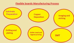
- Flexible PCB fabrication requires several stages, including:
1. Substrate preparation
Substrate materials are made that are polymer sheets like polyimide. For making traces on the substrate it is cleaned and covered with an adhesive substance layer.
2. Copper deposition
- The thin coating of copper is applied on substrates through the use of electroless copper plating. Conductive lines that connect different components is made with the copper layer.
3. Imaging and etching
- In this step circuit design shifted on a substrate with the use of a certain printing technique. Photoresist materials are used for transfer design on the copper layers that are made for showing points where copper-etched
4. Drilling and plating
- For vias creation that makes the connection of layers on the circuit, drilling holes on a substrate for component connections
5. Solder mask
- Solder mask is applied for covering copper traces and components printing on board where label exists
6. Surface Mount Technology (SMT)
In this step, components are connected with the use of SMT on a flexible board. With the use of Pic and place machine accurately connect components on board
Structure of a flexible PCB
The flexible PCB board comes with single-layer, double-layer, or multilayer boards. The main components of single-layer flexible boards are
dielectric substrate film:
The base materials of the board used polyimide material, which comes with high resistance to traction and temperature.
electrical conductors:
It is made with copper and denoted traces of the circuit
protective layer,
It is made with the use of a cover coat
adhesive material (polyethylene or epoxy resin), employed for the connection of parts of the circuit together.
Advantages of flexible PCBs
Flexible boards can easily bend and help to make different design configurations and easy connections. Flexible circuits also come with small or irregular-shaped capes, that are not offered by rigid boards.
The main benefit of flexible circuits is they cover less space, and reduce the weight of the board. The use of available spaces provides good thermal management, reduces chances of head dissipation
These boards offer more flexible operation than rigid boards and easily handle vibrations and mechanical stress.
The interconnection standard process based on soldered wires and hand-wired connectors is replaced with flexible boards.
They are low in weight and thickness are come with high mechanical resistance and high resistance for high temperatures.
Types of Flexible Board
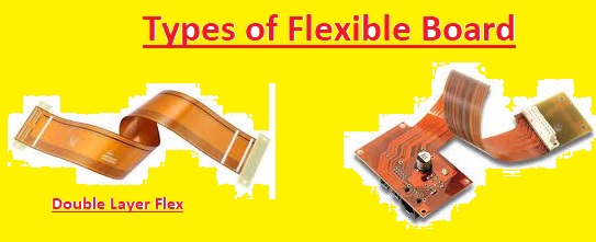
Single-Sided Flexible Circuit Boards:
- It is the basic type of flexible baord that comes with a single layer of flexible polyimide layer in a thin layer of copper. The conductive layer is easy to access from one side of the board
Single-Sided Flexible Circuit Boards with Dual Access:
- These circuits are single-side and copper sheets or conductive materials are easy to access on both sides
Double-Sided Flexible Circuit Boards:
- These boards come with two layers of conductive on every side of the base polyimide layer. The electrical connection between 2 conductive layers is made with the use of metalized plated through holes.
Multi-Layered Flexible Circuits:
- These boards are made with the use of different double-sided and single-sided flexible circuits. These boards are interconnected through plated through holes or surface mounted in a cohesive pattern
Flexible PCB from JLCPCB
- If you have a project that needs a flexible board but the budget is low to afford PCB that not worry. here i am providing you with a 25-dollar discount for a flexible board that is of high quality and has proper features. These discounted and quality boards can be obtained from JLCPCB
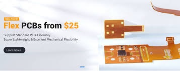
- There are currently new base materials that come at JLCPCB for consideration of customers. FPC board which comes with a high level of dependability and good mechanical flexibility, is provided by JLCPCB and is ready for engineers with their good project demands.
- High-quality flex boards can be obtained from JLCPCB for a low cost starting from 25 dollars. It also supported flexible board projects as standard PCBA.
- For an immediate quote, submit the Gerber file here: https://cart.jlcpcb.com/quote?checkedPlate=7. Join today to receive new user discounts of up to $54.
- You can get a flexible board with high quality on JLCPCB, that is made with quality raw materials from higher supplies over the world. That provides good flexibility and ulta low weight PCB taht can bent to match certain electrical designs in the best way.
- JLCPCB flexible baord offers high performance and quality since comes with comprehensive AOI and flying probe testing for each flexible board. The minimum trace width and spacing are 0.08/0.08 mm.
- EMI protection polyimide stiffness FR4 stiffeners stainless tell stiffeners, and JLCPCB FPC are compatible. They are providing new users 54 dollars OFF sign-up gits. For registering and getting all board coupons in one place “Get Coupons” on the right.
JLCPCB Flex PCB Manufacturing Capabilities
Flexible PCB Capabilities
Feature | Capability |
|---|
Overall size | 8×12 mm to 234×490 mm |
Minimum trace width/spacing | 0.08/0.08 mm (0.10/0.10 mm for 1 oz Cu) |
Through-hole diameter | 0.20~6.50 mm (tolerance ±0.05 mm) |
Minimum slot width | 0.6 mm |
Minimum annular ring | 0.1 mm |
Copper-to-hole clearance | 0.2 mm |
Soldermask expansion | 0.1 mm (single-sided) |
Minimum solder bridge | 0.3 mm (any solder bridge narrower than this will be removed) |
Minimum text thickness & height | 0.1/0.7 mm |
Pad To Silkscreen | ≥0.15mm |
Quality control | Fully AOI & flying probe tested |
FPC Outline | Laser cut (tolerance ±0.1 mm; copper to edge ≥ 0.15 mm) |
Single-Sided Flex PCB
Layer | Thickness(mm) | Note |
|---|
ENIG | 1μ” / 2μ” | Nickel thickness: 80~120u” |
Silkscreen | 10 μm | White |
Polyimide (external) | 12.5 μm / 25 μm | Yellow/black (opaque) |
Adhesive | 15 μm / 25 μm | / |
Copper | 0.5 oz / 1 oz | Electrolytic copper |
Polyimide (internal) | 25 μm | / |
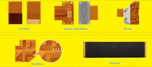
Stiffener | 0.05~0.25 mm (Drawing required) | Support Polyimide / FR4 / stainless steel / 3M tape |
EMI shield | 18 μm | single- / double-sided |
Total thickness | 0.07 / 0.11 mm | Excluding stiffener |
Double-Sided Flex PCB
Layer | Thickness(mm) | Note |
|---|
ENIG | 1μ” / 2μ” | Nickel thickness: 80~120u” |
Silkscreen | 10 μm | White |
Polyimide (external) | 12.5 μm / 25 μm | Yellow / black (opaque) |
Adhesive | 15 μm / 25 μm | / |
Copper | 0.33 oz / 0.5 oz / 1 oz | Electrolytic copper |
Polyimide (internal) | 25 μm | / |
Copper | 0.33 oz / 0.5 oz / 1 oz | / |
Adhesive | 15 μm | Yellow / black (opaque) |
Polyimide (external) | 12.5 μm | / |
Silkscreen | 10 μm | White |
ENIG | 1μ” / 2μ” | Nickel thickness: 80~120μ” |
Stiffener | 0.05~0.25 mm (Drawing required) | Support Polyimide / FR4 / stainless steel / 3M tape |
EMI shield | 18 μm | single- / double-sided |
Total thickness | 0.11 / 0.12 / 0.20 mm | Excluding stiffener |
Credit to JLCPCB
JLCPCB Flex PCB Ordering Instruction
- if you are choosing adhesive ness electrodeposited copper has ENIG surface treatment for the base conductor. Overlapping silkscreen wiring on ENIG pads will carve out hollows in the pad.
- The FPC edge must be 0.2mm from the exposed connection pads. Over that distance, areas will reduce.
- Optional extras come with an EMI shield and stiffeners. For stiffeners, they must be defined through distinct CAD designs or distinct Gerber layers that are configured with the material and thickness required. The stiffener types are can seen here
Material of flexible PCB
- The famous material for the flexible board is polyimide and best for differnt applications since has flexibility, thermal stability, and chemical resistance.
- Polyester is used for low-end projects because it is low cost as compared to PI. It is low thermal stable and more flexible than PI
- Liquid crystal polymers are used that operate on high-temperature conditions and offer dimensional stability, so it is best for highly reliable circuits. It is high prices as compared to PI and PET.
- Good electrical features help PTFE a good material for high-frequency uses. It has less flexibility and higher cost as compared to other materials.
Flexible PCBs Comparsion with other PCB Boards
- Here we have made a detailed comparison table between flexible PCBs and other types of PCBs:
| Feature | Rigid PCB | Flexible PCB | Rigid-Flex PCB |
| Board Material | FR-4 | Polyimide | FR-4 + Polyimide |
| Board Thickness | 0.2-6mm | 0.05-0.5mm | 0.4-4mm |
| Bending Capability | Not Flexible | Highly Flexible | Flexible |
| Number of Layers | 1-50+ | 1-8+ | 2-20+ |
| Cost | Lower | Higher | Higher |
| Design Complexity | Limited | Limited | High |
| Weight | Heavy | Light | Light |
| Component Mounting | Surface Mount | Surface Mount | Surface Mount |
| Trace Width/Spacing | 0.1mm/0.1mm | 0.05mm/0.05mm | 0.1mm/0.1mm |
| Thermal Resistance | Good | Good | Good |
| Signal Integrity | Good | Good | Good |
| Reliability | High | High | High |
| Environmental Limits | Limited | High | Limited |
Flexible PCB Electrical Features
Dielectric Constants (Dk):
- This feature defines speed when an electrical signal moves from flexible boards. flexible board such as polyimide, comes with a lower Dk than FR, and material used for rigid-flex boards, which helps the highspeed signal transmission. The dielectric constant of base materials also affects FPC impedance.
Loss Tangent (Df):
- This value is based on energy lost in the form of heat when the signal moves through the FPC circuit. The low Df means a lower single loss and good signal quality. FPC has a lower DF value than rigid boards and is best for high-energy solutions.
Conductivity:
- The electrical conductive of copper traces in FPC measures features to carry current. FPC supplier uses high-conductivity copper to reduce signal losses and make sure efficient current flow.
Thermal Stability:
- It features to handle high temperature that increases board reliability for manufacturing and end-use.
Tensile Strength:
- They are robust materials irrespective of flexibility, resistant to mechanical stress like stretching and tearing during manufacturing and applications
Flexibility:
- Core featues that help boards to be used for new electronic board designs without affecting due to bent or folded.Read our More Engineering Blogs

1 Comment