 Hi, students welcome to another interesting post. In today’s post, we will discuss the Operation of Integrators and Differentiators. The operational amplifier integrator is used in the simulation of different category of mathematical integration that is summation techniques used to find the net area covered by the curve. The operational amplifier differentiator circuit does the simulation of differentiation of different functions, It defied as the technique that finds the instantaneous rate of change of a function.
In this post, we will discuss the operation of integrator and differentiator. The ideal category of these 2 circuits is used to represent some basic rules. In a practical integrator, there is extra resistance in parallel combination is linked with the feedback capacitor to stop the saturation process. While in practical differentiators s the resistance is linked with the comparator in series combination to decreases the large frequency noise. So let’s get started with Describe Operation of Integrators and Differentiators.
Operational Amplifier Integrator
Ideal Integrator
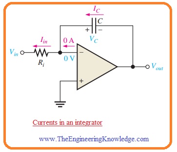
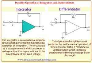
- The circuit representation of the ideal integrator is shown in the below figure.
- You can note that in the circuit the feedback component is a capacitor that makes the RC circuitry through the input resistance.
Capacitor Charging Process
- For a practical understanding of the integrator, it is necessary to revise the charging process of the capacitor.
- As we know the charge stored on the capacitor is in direct relation with the current Ic in the capacitor in respective time t.
Q = ICt
- In case of the voltage value of charges will be given as.
Q = CVc
- If we combine these 2 equations than the value of voltage across the capacitor will be.
VC = (IC/C)t
- This relation is in the shape of the equation that is a straight line which is started from 0 having constant slope Ic/C.
- As we know that the equation for the straight line is y=mx+b.
- In this condition, the y=Vc, m=Ic/C, x=t, and b is zero.
- As we know that the waveform of capacitor voltage in RC circuitry is not a straight line but exponential.
- It is due to that charging current value regularly reduces with the charging of the capacitor and it causes the rate of change of voltage to reduce regularly.
- The main point to use an operational amplifier with the RC circuitry for the creation of an integrator is that the value of current used for capacitor charging is constant that generates the linear voltage than the exponential voltage.
- Let us prove this statement true.
- In belwo figure the inverting input of the operational amplifier is connected with the ground therefor value of voltage about resistance Ri is Vin.
- So value of input current will be.
Iin = Vin/Ri
- If the value of Vin is constant then the value of Iin is constant since the inverting input has a value of zero volts through retaining the constant value of voltage about the resistance Ri.
- Due to the large value of input impedance of operational amplifier, the very small amount of current is inverting terminal.
- Due to this net current flows through the capacitor, it can be seen in the above figure.
- Hence
IC = Iin
Capacitor Voltage
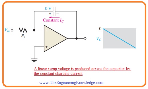
- As the value of the current Iin is constant. The constant Ic charges the capacitor in a linear way and generates a linear voltage about the capacitor.
- The positive terminal of the capacitor is at zero volts through the virtual ground of the operational amplifier.
- The voltage at the negative terminal of the capacitor that is voltage value at the output of the operational amplifier reduces from 0 when the capacitor gets charged it can be seen in the below figure.
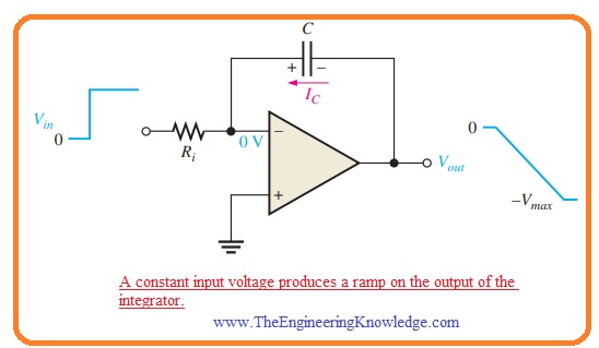
- This voltage Vc is known as a negative ramp and is a result of constant positive input.
Output Voltage
- The value of Vout similar to the voltage at the negative terminal of the capacitor. When the positive voltage in input voltage in the form of a pulse is given the output ramp reduces in a negative manner till the operational amplifier gets saturated in an extreme negative point. It can be seen in the below figure.
Op-Amp Differentiator
Ideal Differentiator
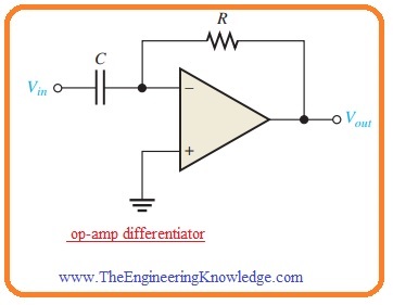
- In below figure the circuit configuration of ideal differentiator is shown.
- You can see that the position of capacitor and resistance is different from the integrator. In this condition, the capacitor is input component and resistance is operating as a feedback component.
- The differentiator generates an output which is directly proportional to the rate of change of input voltage.
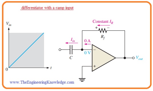
- To observe the working of differentiator give the positive ramp voltage at input terminal as it shown in below figure.
- In this condition the Ic is equal to current Iin and voltage about the capacitor is equal to the Vin as the virtual ground is linked at the inverting input.
- According to given formula VC=(IC/C)t the value of capacitor current will be.
IC = (VC/t)C
- As the current at inverting terminal is ignorable IR=IC. Both current has constant value since the slope of the capacitor voltage has a constant value.
- The output voltage has a constant value and equal to the voltage about the Rf since the one terminal of feedback resistance is at zero volts.
Vout = IRRf = ICRf
Vout=- (VC/t) RfC——-A
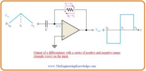
- the value of output is negative in case of positive input and positive when input is negative-going ramp it can be seen in below figure.
- In case of a positive slope of input, the capacitor gets charged from the input supply and constant current in the feedback resistance in the respective direction.
- In case of a negative slope of input, the current is flowing in reverse direction since the capacitor is getting charging.
- In equation A’ you can note that the value VC/t is the slope of input.
- If there is an increment in slop then Vout reduces. If slop reduces than Vout reduces.
- The output voltage is in direct relation with the slope.
What is Practical Differentiator
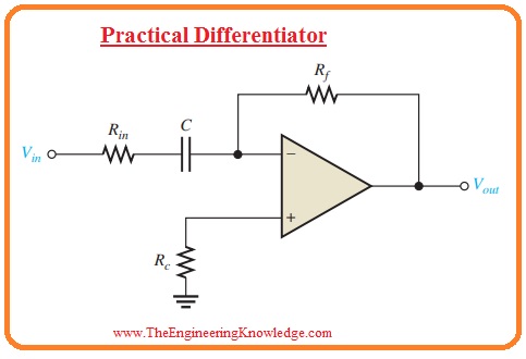
- The ideal differentiator comprises of the capacitor in series combination with the inverting terminal.
- Since the impedance of the capacitor is very less in case of large value of frequency, the combination of Rf and C creates a large value of gain amplifier for large frequency value.
- It denotes that a differentiator circuitry causes noise since electrical noise generally comprises of large value frequency.
- The method for overcoming this issue is to the addition of resistance Rin in sequence to the capacitor to cause minor effect at the required signal.
- The circuit configuration practical differentiator is shown in the below figure.
So friends that is detailed post about Operation of Integrators and Differentiators if you have any query ask in comments. See you in next post have a good day.

