 Hello, readers welcome to the new post. In this post, we will have a detailed look at Introduction to 555 Timer. It is used in different circuits to provides the features like time delay pulse and oscillation that are its main specifications. It consists of transistors, resistances, and capacitors in its internal configurations. It is the main parts of circuits like DC to dc conversion and detectors,
In this post, we will discuss its working, pinouts, applications, and other parameters. So let’s get started with Introduction to 555 Timer.
Introduction to 555 Timer
- The 555 timer is integrated circuitry used in such applications where usage of pulse, delay of time and oscillation is needed.
- There are 2 modules of 556 in single packaging and four 558 modules in a single casing.
- The first time it was used in 1972. There are many manufacturers are creating this device.
- There are normally twenty-five transistors fifteen resistances and two diodes are positioned a single board.
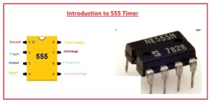
- This board comes up with eight pinouts that are dual inline packaging.
- Some modules of these categories like 556 come with fourteen pinouts and 558 has sixteen pinouts.
- Its temperature range where it works is between zero to seventy centigrade.
- The voltage range for which it operates is 4.5 volts to fifteen volts dc.
- There are flip flops, voltage dividers and comparators are configured at the board of this device.
- normally it employed to offer the time delay where it used.
- It operation modes are monostable, bistable.
- It comprises of 3 resistances of five kilo-ohms in series combination to voltage dividers modules so-known as 555 timers.
- It provides the larger value current at the output terminal so used to operates TTL.
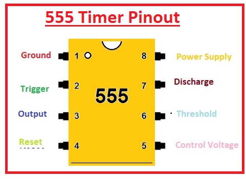
555 Timer Pinout
- There are eight main pinouts of this IC that are listed here with the details.
Ground
- This pinout is linked to the ground and zero volts exist at this pin.
Trigger
- The value of the voltage at this terminal is less than or has to control volts there is will be high at the output.
Output
- The output of the timer is taken out from this pin.
Reset
- It is employed to reset the timer.
Control
- There is an internal voltage divider that exists in this board that is linked to the outer circuit through this pinout.
THRESHOLD
- If the voltage at this pin is high than control then the output becomes low.
DISCHARGE
- The capacitor is being discharged through this pinout.
Vcc
- Positive volts are given here.
555 Timer Modes of Operation
555 Tiemr has three modes of operation
Astable Mode
- In this mode of operation there is no stable level exists at output and output will be between high and low. The signal at the output terminal switches to low and high without any application of an outer trigger. There is a continuous pulse generated according to the values of resistors and capacitors connected in circuitry.
Monostable Mode
- This mode of operation of 555 timers has stable and unstable conditions. If the output is high at a stable then the output of the timer is high. There is a single pulse generated when the indication is given to the timer from the trigger button input
Bi-stable modes
- In this mode, the timer has stable output states. During every interrupt, output varies from low to high respectively for high output. If it is low get the interrupt and retain the low state till other interrupts vary the states. This mode of operation is also called Schmitt Trigger mode. It is used for applications where the load is continuously on and off through the use of a push button
Schmitt Trigger
- In this mode work as an inverter that transforms the distorted input to digital.
555 Timer Features
-
555 Timer Features
Some features are discussed here
- The operating volts of this timer is plus five volts to plus eighteen volts
- The load current is about two hundred milliampere
- The output of the timer can be operated through TTL since it has a high current
- Its temperature stability is high about 50 parts per million per degrees Celsius. Its operating temperature range is 55 C to 125 C and temperature stability is 0.005% per 0C
- Its duty cycle can be varied
- The highest power dissipation for one unit is 600 milliwatt
- It can operate in stable and monostable modes of operation.
- It comes in DIP packaging have eight inputs, and fourteen pinout dual in-line packaging
555 Timer Applications
- Here are some applications of the 555 timers explained that will help to use this component in different projects like latch circuits.
- 555 timer used in temperature sensor to measure the temperature values at different places.
- It is used for the generation of the square, waveform, and pulse signals.
- It is used as a quad-timer circuit.
- It is part of an analog frequency meter.
- It used in digital logic probes
- It used in flip-flop circuits
- It used in time delay circuits
- It is part of the lamp dimmer
That is all about the 555 timers. I have explained each and every factor of this module in detail. if still have any issues ask in the comments. Thanks for reading have a nice day. see you in the next post.


