 Hello, readers welcome to the new post. In this post, we will have a detailed look at a single diagram or one-line diagram in an electrical power system. There many components used in our power system like generator, motor, transformer, transmission line, and other protection devices. To have a deep understanding of circuitry having these elements is the main fact. As their connection make the system complicated to easy understanding of these components and their connection single line is drawn that is easy way to understand the system.
In the single line diagram, there is all component used in the circuitry is drawn and their connection is done to get the working of the system and its different component. In this post, we will cover different aspects of the system and their component used. So let get started with Single line diagram.
SINGLE-LINE OR ONE-LINE DIAGRAM Electrical Power System
- The balanced three-phase system is understood through the use of a single-phase resultant system that consists of any one line of three phase system and one neutral as returning path. It is generally one line is drawn to have an understanding of single-phase system
- it is simple to use line and neutral with different components through drawing the different components used in the circuitry in symbolic representation in place of resultant circuitry.
- The main parameters of circuitry are not drawn and lines of transmission is denoted through a single line among transmission and receiving points.
- The one line is drawn and components of the system are shown at line
- The main importance to use a single line diagram is to discuss the main parameters of the system and its elements.
- If we are discussing the load of the system then in case breakers and relays are not drawn on line since it has no importance but in case of there is transient existing in the system has to be stable so the drawn os relay and the breaker is important since it defines the circuitry operation.
- In certain cases, there is a drawing of the current transformer and potential transformer is done that used to finds the current and voltage of system.
- The data shown at the one-line diagram should be according to system requirements and the part of the system that we are going to discuss it makes simple to study the system
SINGLE-LINE OR ONE-LINE DIAGRAM Components
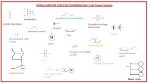
- The below diagram indicates the symbols of the component that are drawn at the single diagram.
- The symbol used for different electrical machines like motor and generator is a circle and some other devices symbol are shown.
- During making a single line diagram there is knowledge of the connection for the ground to the system should be known that helps to find the current direction if an unsymmetrical error occurs in the system.
- The standard symbolic representation to define the three-phase system having Y configuration connection with neutral is shown in above diagram.
- In some cases, transformer solid ground configured and in some cases has through high-value resistance and in certain cases through an inductance coil
Single Line Diagram
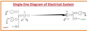
- In below figure single line diagram of a simple power system is shown.
- There are two generators connected and have grounded configuration through reactor and resistance each.
- they are linked to the transmission line through bus and step-up transformer
- There is generator connected and linked to ground through reactor and link to bus and to other ends of the line with transformer.
- The load is linked to the bus with that the load’s ratings of generators and transformers and reactance and other elements of the system is shown
That is all about the single line diagram of you have any further query ask in the comments thanks for reading have a nice day


