 Hello, learners welcome to new tutorial. In this post, we will learn PCB Design in Proteus. PCB is considered as the very basic part of any project since all parts of the project are positioned on the board. It is very necessary all parts are configured on the boards very accurately and fully. If not done there will be a change of errors that our projects will not configure accurately.
SO minimize the errors chance of errors occurring in the projects created on the PCB there must be its testing phase done on the proteus softwaers means, first of all, we design our projects should design on the proteus by making the PCB that will helpful for us to understand the working of our projects. IN this post we will give a detailed overview about making the PCB in the proteus that will be helpful for us to design our projects practically. So let get started
PCB Designing in Proteus
- There are some steps we have to follow that are listed here with the details.
- In below diagram you can see the normal layout of proteus
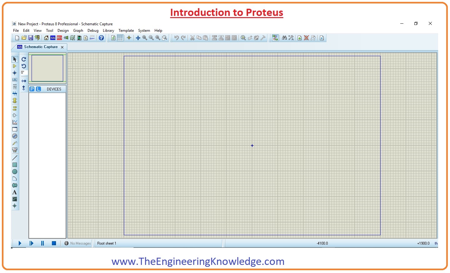
- In this normal layout first of all we make projects that will gain created in PCB layout
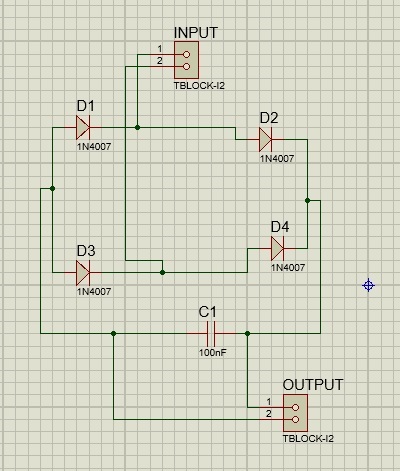
- Components of the project are listed here
- 1n4007 diodes quantity 4
- capacitor 100uF
- tblock
- Now we will make a circuit by connecting these components
- The circuit can see here by joining the above-mentioned components
- In below figure you can see red color PCB layout pressed on it then PCB layout of black colors will be open can seen here
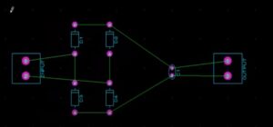
- Here you can see the component of our projects that we made in a normal layout.
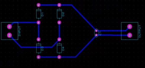
- Now we have made project in PCB layout and it looks like this configuration

Final overview of our project can see here in the PCB layout form
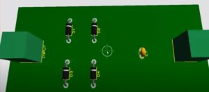
- Three-dimensional layout of our project can be seen here
Can I design PCB in Proteus?
- The proteus design is commonly used for different industries as low-cost option for professional PCB design and also for a rapid prototyping tool for research and development.
Which software is best for PCB design?
- The commonly used software options for PCB designs are Altium Designer, KiCad, Eagle PCB, OrCAD, and EasyEDA.
- These tools provide a good range for making schematics, drawing circuit boards, and producing manufacturing files. For new PCB designer best is to use KiCad Professional
How to use Proteus for circuit design?
- First of all Installing Proteus 8.0.
- Getting Started with new files
- Placing the Components in layout
- Making the Schematic.
- Preparation for PCB Design.
- PCB Designing
- 3D View.
- Printing Out PCB for Etching
Is Proteus better than Altium?
- It is based on functions that you need and applications. Altium Designer provide add-ons with important features, proteus PCB design work on customization.
Can I design my own PCB?
- Yes it is possible to make own PCB layout with use of any PCB design software. best is to use eagle layout editor but if you not have more experience for tool can use Microsoft Powerpoint.
How to convert schematic to PCB in Proteus?
- First of all open the proteus schematic and choose the PCB layout option in the toolbar menu.
- Proteus will promptly make a new PCB layout file.
- The software will automatically make a PCB layout according to the components and connections in the schematic.
Is Arduino a PCB?
That is all about the PCB Designing in Proteus. I have explained all points with the details. If you have any further query ask in the comments, thanks for reading have a nice day