 Hello, friends welcome to the new tutorial. In this post, we will learn about Introduction to ODB-II Connector. The full form of OBD is onboard built-in diagnosis. It is diagnosis modules that are employed in currently used cars. It helps to regulate and observes the speed mileage and fuel emission report of cars.
It also helps to monitor the performance of the engine. It is also called ECU or engine control unit. Here we discuss its different features, pinouts, and practical applications. So let’s get started with Introduction to ODB-II Connector.
Introduction to ODB2 Connector
- OBDII is a diagnostic module that is used in different types of cars to monitor the operation of that car.
- The get through these modules from the engine control unit helps to make the overview of cars when any fault exists in that car.
- For practical observation, these modules look at your car dash where it exists.
- It relies close to the steering wheel of a vehicle and can also exist close to covers
- Before making the male connectors to OBD2 female connectors make sure they fit to this category.
- The pinout number sixteen of this module gets the power from the battery of the car.
How to Log OBD II data
- There are some processes to log in the data.
- First of all links the OBD2 logger with the connector
- Send the request frames through the CAN
- The correspondent engine controls negative response frames through CAN.
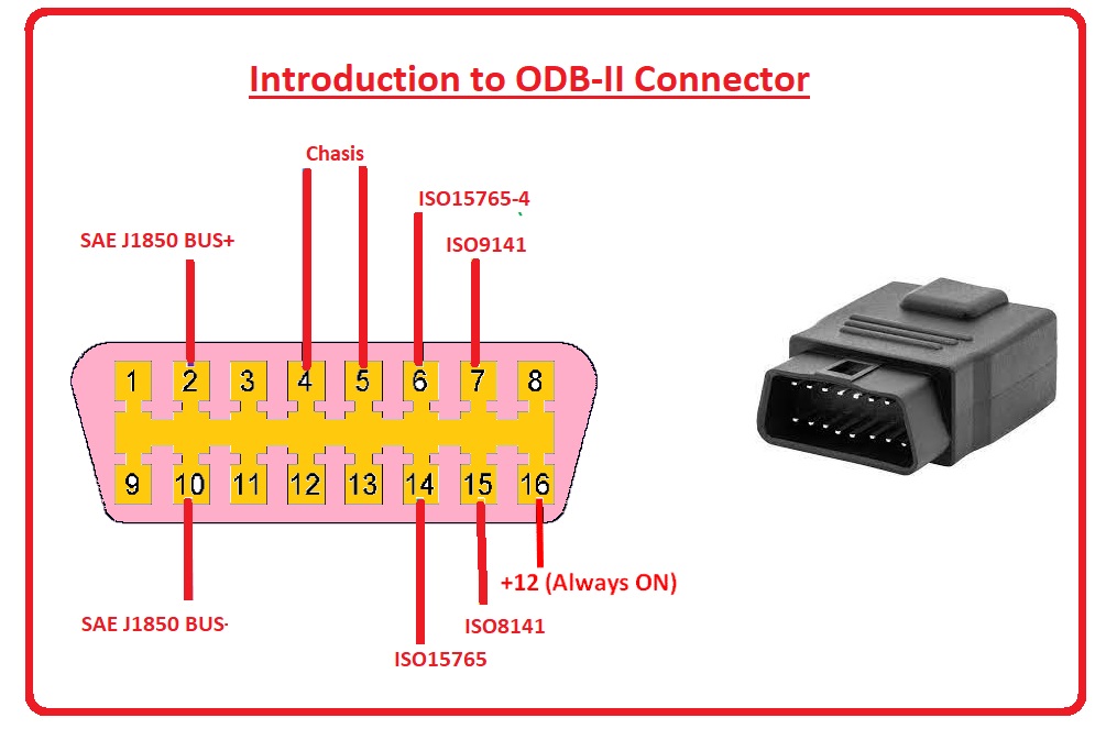
OBD2 Pinouts
- The pinout details are explained here
| Pin Number | Name of PIn | Explanation |
| 1,3,8,9,11,12,13 | Blank | All those pins are nonstandard and vendor specifications. It does not need normal interfacing |
| 2 | SAE J1850 Bus+ | it uses variable pulse width and generally comes in GM vehicles. It is a positive pin |
| 10 | SAE J1850 Bus- | it is a negative pin used by GM vehicles and comes with the use of variable PW |
| 4, 5 | Ground | here ground is connected to the complete car system |
| 6 | ISO15765-4 CAN High | There is a wire CAN protocol at one Mbps speed followed by this pin and is the high pinout |
| 14 | ISO15765-4 CAN Low | it is CAN low pin and uses a 2-wire CAN protocol at 1Mbps speed. |
| 7 | ISO 9141 – K Line | asynchronous serial communication protocol, followed by this |
| 8 | ISO 9141 – L Line | it also follows asynchronous serial communication protocol, |
Types of OBD2 Connectors:
OBD2 Connector Type A and Type B
- Type A of OBD2 connector is used in cars and type B is used in heavy vehicles also in medium vehicles. These two types come with the same pinout but the output supply for them is different. Type A works on type A and Type B on 24 volts
- Type A has a 500K baud rate and type B has 250K.
How Does an OBD2 Connector Work?
The OBD2 gets data from differnt sensors and monitoring components connected engine of the car and other parts. If any issues occur OBD2 computer system analyzes data and DTC or diagnostic trouble. These codes can be read with the use of diagnostic tools that help to find connection issues with car operation
it is done by a connection tool with an OBD2 port that is configured below teh dashboard of the car. The OBD2 prot comes with standard pins that help to connect the diagnostic tool with an onboard computer and get DTC
The pinouts of PBD2 help how every pin on OBD2 functions. There aer 16 pins that do their own function pins 4 and 5 are employed to make ground connections and Pins 2 and 10 are for interfacing with the inter-computer of the car. Pin 6 and 14 are used for the connection of the CAN bus
How to read OBD2 DTC Codes?
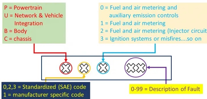
There are 4 types of codes. The First DTC character is a letter. There are four types of codes:
- P codes: it is a problem with the powertrain. That can be, transmission, engine drivetrain, and fuel system.
- C codes: It denotes the issues with the chassis. it includes steering, suspension, and braking.
- B codes: B indicates that there is a problem with the body of the car. That is in the passenger compartment area.
- U codes: it is an issue with the vehicle’s onboard computers and integration functions which is managed by OBD
2nd DTC character
can be zero or one but are numeric digits.
- 0: Zero is the standard SAE international code. that is a generic code, so it applies to all vehicles that is supported by teh OBD-II international standard.
- 1: it is the car’s make or model. Also called enhance code, not lie in SAE standard.
3rd DTC character
If the 2nd DTC character is a zero then the 3rd character helps to find malfunctioning subsystems. That can be 8 digits
4th and fifth DTC character
These are two-digit numbers from zero to 99 that are called the Specific Fault Index. it helps to find the accurate error of a car or any vehicle
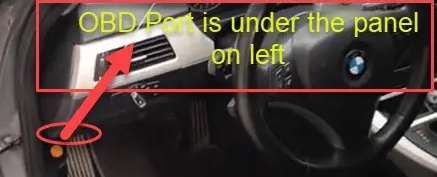
Where is the OBD2 port located in a car?
The OBD-II port normally exists under the dashboard, below the steering wheel column shown in the figure
OBD2 vs CAN bus
- For board diagnostics, OBD2 is a high-layer protocol and CAN is a technique for communication.
- The OBD2 standard defines an OBD2 connector, as a set of 5 protocols that can operate. Since 2008, the CAN bus has been used as the main protocol for OBD2 in all cars sold in the US.
Five OBD2 protocols
ISO 15765 (CAN bus):
- It is necessarily used in US cars since 2008 and still in different cars.
ISO14230-4 (KWP2000):
- It was common protocol for2003+ cars in e.g. Asia
ISO9141-2:
- It was used in EU, Chrysler & Asian cars in 2000-04
SAE J1850 (VPW):
- It was part of some older GM cars
SAE J1850 (PWM):
- It used in older Ford Cars
How to log OBD2 data?
- Make the connection of OBD2 logger with OBD2 connector
- The use of the tool has a feature to send ‘request frames’ through CAN
- The related CUs send ‘response frames’ through CAN
- Decode the OBD2 responses through OBD2 DBC
Read Also
- Best Way How to Get Bugs Off Car Home Remedy?
- Comparison Between Spectrum Mobile vs T Mobile Carrier
- How to pair an iPhone with your car in different ways
- How to Install Apple Carplay on Iphone
- How Much Do Car Batteries Weigh? (Different Battery Types)
Faqs
- Vehicles sold in the USA after 1996 come with an OBD2 port. it is called an OBD-II port and is used for the connection of dedicated devices for retrieve data from the onboard computer
- OBD2 comes with comprehensive diagnostics, monitoring of different vehicle functions, and early detection of potential errors. leveraging OBD2, we can increase fuel efficiency, ensure compliance with emission standards, and maintain vehicle safety.
- OBD II is an acronym for On-Board Diagnostic II, it is 2nd generation of on board self-diagnostic instruments needed for light- and medium-duty California vehicles
- The OBD1 system is basic and less effective thatn the OBD2 system. The OBD1 system is used for monitoring emission control systems, and the OBD2 system monitors different types of engine and emission control systems as well as transmission, ABS, and airbags.
- It can start a car based on the distance to car like 100 meters far.
- All cars and light trucks created and sold in the USA after 1, 1996 come with OBD II. Normally all 1996 model year cars and light trucks are supported if built in late 1995.
- The OBD 2 scanner can direct accurate direction. Check engine light appears on the dashboard enough to dampen any drive.
Can I use OBD2 while driving?
- The device has the feature of running basic diagnostics with the engine off, it can unlock its full potential when the engine is running or in “Accessories” mode.
- Its main advantages are early diagnosis to solve problems before becoming harsh and high support for cars with OBD-II system. The OBD-II system comes with an efficient fleet management system as compared to traditional GPS tracking systems.
- OBD2 provides a standard hard interface, a female 16-pin (2×8) J1962 connector, here type A is used for 12-volt vehicles and type B for 24-volt vehicles.
- The OBDII computer monitors the vehicle emission control system in real time and has features to inform motorists or technicians of a systematic problem if occurs. The system operated through indicator lights, drive cycles, trouble codes, and readiness monitors.
What are the 10 modes of OBD2?
- Mode $01 – Request Live Data
- Mode $02 – Request Freeze Frames
- Mode $03 – Request Stored Trouble Codes
- Mode $04 – Clear/Reset Stored Emissions Related Data
- Mode $05 – Request Oxygen Sensors Test Results
- Mode $06 – Request On-Board System Tests Results
- Mode $07 – Request Pending Trouble Codes
- Mode $08 – Request Control of On-Board Systems
- Mode $09 – Request Vehicle Information
- Mode $0A – Request Permanent Trouble Codes
- This device uses power when it is connected in OBD2 port. The manual defines 45mAmp maximum current drawn. The standard car battery powers it for about 1000 hours, and drains at end.
Note that cars differ by model/year in what OBD2 PIDs they support. For details, see our OBD2 data logger guide.


