 Hello, readers welcome to new post. Here we will have a look at Latch Circuit using 555 Timer. There are various types of components that are commonly used in electronic projects and circuits and we know them, one of them is the 555 timer IC. Its common operation types are monostable, multistable and bistable. With this, it is also used for switching operations. It works like a switch, if we press it, then we start to control the circuit and when we press it again, the circuit breaks like a normal switch. It is also used in digital electronics to control various components such as Arduino controllers and other types of sensors.
Here we will use 555 timers and create a latch circuit and discuss its operation. But before we discuss the circuit first we will learn the introduction of 555 timer which helps to get the details of the circuit
Introduction to 555 Timer
- The 555 timer is an integrated circuit used in such applications where the use of pulse, time delay and oscillation is required.
There are 2 modules of 556 in one package and four modules of 558 in one case.
- It was first used in 1972. There are many manufacturers who create this device.
Usually, there are twenty-five transistors, fifteen resistors and two diodes located on one board.
This board comes with eight leads that are a double inline package.
Some modules of these categories like 556 come with fourteen pinouts and 558 has sixteen pinouts.
Its temperature range where it works is between zero and seventy degrees Celsius.
The voltage range for which it operates is 4.5 volts to 15 volts DC.
Flip-flops, voltage dividers and comparators are configured on the board of this device.
normally used to offer a time delay where used.
Its operating modes are monostable, bistable.
It consists of 3 resistors of five kilohms in series combination to voltage divider modules, known as 555 timers.
It provides a larger value of current at the output terminal, so it is used for TTL operation
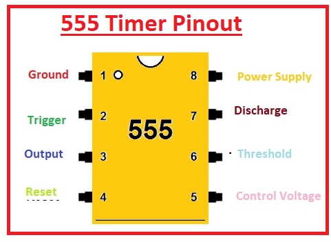
555 Timer Pinout
Ground
- This pinout is linked to the ground and zero volts exist at this pin.
Trigger
- The value of the voltage at this terminal is less than or has to control volts there is will be high at the output.
Output
- The output of the timer is taken out from this pin.
Reset
- It is employed to reset the timer.
Control
- There is an internal voltage divider that exists in this board that is linked to the outer circuit through this pinout.
THRESHOLD
- If the voltage at this pin is high than control then the output becomes low.
DISCHARGE
- The capacitor is being discharged through this pinout.
Vcc
- Positive volts are given here.
555 Timer Latch Circuit components
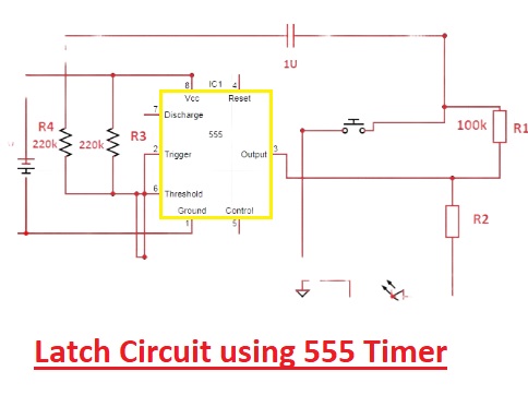
Now have a look atthe latch circuit
The components of the circuit are listed here
- 555 Timer
- LED
- Resistors
- SPDT Relay
- 1n4007 Diode
- BC557 PNP transistor
555-Timer Latch circuit Working
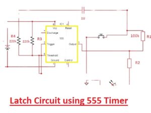
- In this circuitry, the 555 timer is the main part and this circuit is working like the toggle. The main components of the circuit are the SPDT relay diode that is working as a diode. The resistance 220-kilo ohm is working as a voltage divider. That voltage divider provides the output signal to pin out six timers. When the circuit is on output is off state, After that, the button is pressed capacitor gets charged and makes the unbalanced state. Voltage changes at pinout 2 cause the output to on. So when the again button is pressed that results in voltage detection at pinout six of the charged capacitor and switch off the outputting.
- This circuit is the logic circuitry that comes with two inputs called set and reset inputs. Latch circuits have two types active high and active low. In active high it is ground and the latch is triggered through high signals. While in the case of active low input is high and the latch is a low signal.
Latch circuit Applications
- Some applications of latch circuits are discussed here
- It Used in storage devices like memory units
- Used to encode binary numbers
- Used in digital applications
That is all about the Latch Circuit using 555 Timer all details has explained. If you have any query ask here


