 Hello, readers welcome to the new post. In this post, we will discuss the Introduction to CD 4017 IC. The CD4017 is CMOS decade counter integrated circuit. It is the best option for low-range counting circuit applications. It can count digits from zero to ten as it is a Decade counter. If you use it in any projects it will reduce the area of board and time for the design of circuitry. It is like the Johnson 10-stage decade counter.
In this post, we will discuss CD 4017 IC working, features, applications and some other parameters. So let get started Introduction to CD 4017 IC
Introduction to CD 4017 IC
- The CD4017 is an integrated circuit that is used for counting circuits and can help to count ten outputs according to adjusting the time.
- It also comes with a feature to indicate the status of counting through use of a carry pinout.
- It is used for LED chasers and other logic circuits and it will be a good option to use in circuits where counting up to ten digits is needed
- It is sixteen pins CMOS counter that has ten Johnson counters with ten decoded outputs.\
- Its structure is such that used for counting sequences. The 10/8 decoded outputs will be on in sequence if a clock signal is given at inputs. In simple means outputs are zero states if we provide a clock then goes to high or 1 for each positive edge of the signal every output led will on in sequence.
- The carry-out single of this module is high for each ten-clock input cycle. It has enabled and reset pinout that is used to control and reset the process
CD 4017 IC Features
- It has some features that are discussed here
- It comes in sixteen pinout packages that are PDIP, GDIP, and PDSO
- It uses clock frequency value 5.5Mhz
- Its input supply lies between three to fifteen volts and normally operate on plus five volts
- It can support the 10 decoded outputs
- It is a CMOS Decade counter
CD 4017 IC Pinout
- Its main pinout are discussed here
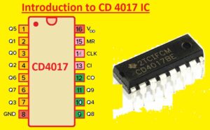
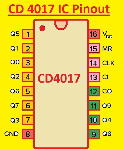
- Pin 1 to 7 and 9 to 11: These pinouts are used as output pinouts to counter the numbers through their on and off status
- Pin 8: It is the ground-connected pinout
- Pin 12: It is carry out input that will be high when this counter completed the counting from one to ten. It works as a carry
- Pin 12: it is enabled pinout that is the input terminal if a high hold count status
- Pin 14: It is clock pinout counter will count if this pin has high. At this input, 555 timers is connected to generate a signal
- Pin 15: It is the rest pinout
- Pin 16: It attached to the input power supply
Digital Dice Circuit Using CD 4017 IC
- Here we will make a Digital Dic circuit through of CD4017 integrated circuit. The component used in this circuit are listed here
- CD4017
- Battery
- LED
- Push Button
- Resistors
- Capacitors
- 555 Timer
- PCB from PCBWAY
- PCBWAY is PCB and PCBA manufacturer company that provides prototyping and low-volume production. Electronic project creators can get the benefits of their quality services by placing orders from 5PCs to get their desired projects. In this field, they are serving for more than one decade. They are fulfilling the requirements of engineering students all over the world.
- PCBWAY is a one-stop PCB assembly and prototyping solution that provides some of the most innovative PCB technology and the highest quality standards in the industry. DFM, Gerber files, bills of materials, invoices, and inspection reports are in your orders.
- Their pricing structure is transparent and contains no hidden costs. Their price is one of the most competitive in the world and is a fraction of what other US or European manufacturers normally charge you. Even many price-sensitive customers such as students and hobbyists rely heavily on us for their PCB prototype, low-volume production, and assembly needs. They strive to save you money and time.
- PCBWays Prototyping Service start from $5/10pcs for Maximum Size 100x100mm Double Sided Custom FR4 PCB. As with many Chinese PCB manufacturers, you need to enter the parameters: Option of nine solder mask colors, white or black screen printing and a range of thicknesses (0.6mm, 0.8mm, 1.0mm, 1.2mm, and 1.6mm; thicker and thinner PCBs available, but will increase the price). The default minimum distance/spacing is 6/6 mil (0.1524 mm), but better tolerances up to 4/4 mil can be ordered at extra cost. The default minimum hole size is 0.3 mm, but again a better specification is available.

- They also come with customer support with live chat option to get the details of your projects and any related service. Their service people will follow your orders from the time you submit your Gerber file to the minute you receive your PCB and assembled PCBs in a satisfactory mood.
-
PCBWay’s quality management system is to ensure efficient printed circuit boards which meet customers’ requirements. Their partners manufacture in compliance with, among others, the following standards:
- IATF 16949
- ISO 9001:2015
- ISO 13485:2016
- REACH
- CE
- RoHS
- UL
- Currently, their Christmas discounts promotion is live must visit that service to get huge discounts for your products. I will suggest you visit this promotion to get quality products at reasonable prices
2022 PCBWAY CHRISTMAS BIG SALE
Digital Dice Circuit
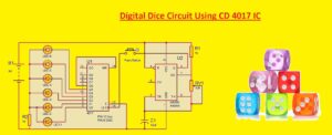
- In this circuit, we are using six LEDs that will denote each fight of dice that are 1 to 6.
- In this circuit push buttons are used to send the clock. When we press the LED signal is given to LEd that glows and when the release button does not glow.
- Through led glow, we can get the dice number such as if we push the button and press then any LED glow that is number four LED in results we can get the dice number 4. In this circuit, we used 6 LEDs with outputs Q0 to Q5
- In this circuit output pin, Q6 is attached to RESET PIN 15. So when all dice number will glow through LED then LED 6 that is reset will start operation from first LED
- In this circuit, there is a 555 timer used that provides the signal at Pinout 14. The output of pin 3 of the timer is given to pin 14 of the integrated circuit that causes the configuration of every clock pulse.
- In this circuit, the potentiometer is used to control the glow speed of LEDs by rotating the knob of the potentiometer to vary the oscillation frequency of the 555 timer results clock signal speed.

CD 4017 IC Applications
- The main applications of this component are discussed here
- It used in LED operators circuits
- Adjustable timers are created by using this device
- It used for unbiased digital dice
- A clap circuit can create by using this component
- It used in medical instruments and automotive
- Used as a binary counter
That is all about the CD 4017 IC all details has explained. If you have any queries ask here. Further, visit PCBWAY to get quality services for your next projects. Thanks for reading have a good day


