 Hello, readers welcome to the new post. Today we will discuss HOW TO USE LED DISPLAY DRIVERS. The display driver is ICs circuit that is used to make connections between eh controller like the microcontroller and display devices. The display driver normally gets programming commands and data through the use of serial and parallel communication interfacing. After this configuration, they generated certain values of the signal by using current volts timing demultiplexing, and the output is shown on display.
The main function of the LED driver is to control the current and volts given to a single LED in the display. in this post, we will discuss all details and related parameters. So let’s get started
HOW LED DRIVERS WORK
- The LED driver operated to control the numerous LEDs at the same time. As we know LED is a current driver component, not a voltage control
- Small changes in voltage can result in high currents. So for this module operation varies the current not volts.
- It is a switch mode component that transformed the input volts value to such a volts value that has current passing in the led equally to drive the current of the led
- The drive current of the LED is used to control its brightness, operation life, and battery charging time.
- The drive current is less than the highest drive current of LED increases the operation life of LED
- LED driver is the same as cruise control used in cars. Its main operation is to control the current movement of the LED.
- If there is no LED driver connected to the led results in heating of the led and unstable operation and at the end led can damage.
- It indicates that without the led driver lead is nothing either it has high quality and good operation.
- Mostly LED is used in fewer volts of dc. Especially the LED driver is used to convert the high-value AC to the low-value dc that is used by led. In simple words it is a rectifier for LED. Led operating volts are two to four volts of dc
TYPES OF LED DISPLAY DRIVERS
- The main types of LED display drivers described here
7 Segment LED Driver
- In these LED display driver combinations, logic circuits are used that get four bit of BCD input and produce 7 segment output signal to regulate the
- These are LED display drivers that use a combinational logic circuit that accepts a 4-bit BCD input and generates seven output signals to control seven individual display segments.
Constant Current LED Driver
- It is an inner circuit that controls every LED loop current and automatically set produced output DC volts to the least value need to make a high forward value
RGB LED Driver
- It is used for control of the color of RGB LED and led strips. Software with inner registers and SPI interfacing used to control the operations
White LED Driver
- It is good for LED matrix control. These modules eliminate white light for backlighting and also have less noise.
Introduction to MAX7219 LED DISPLAY DRIVER
- The MAX7219 comes with a compact structure, serial input, or output common-cathode display driver.
- It can be connected with microprocessors having seven-segment numeric LED displays to eight digits. It also helps processors to connect with bar graph display or sixty-four single LED
- Consists of an on-chip BCD code- B decoder, multiplex scan circuits, digital driver, and 8 x 8 SRAM that is used for data storing
- It uses one outer resistance to adjust the segment current for all LEDs. The MAX7221 has compatibility with SPI communication protocol, QSPI, and microwire and has a value of slew-rate to operate to decrease EMI.
- The simple four-wire serial interfacing link with all mutual ups. Single digits can be addressed and updated without rewriting the complete display.
- It has features to choose code-B decoding or no-decide for every digit.
- The module consists of one fifty microamperes low power shutdown mode, analog, and digital brightness control, and scan limit register which permits users to show from one to eight digits

MAX7219 LED DISPLAY DRIVER Features
- Some features of this component are discussed here
- Storage temperature is minus sixty-five to one-fifty centigrade
- The operating temperature is zero to plus seventy
- Data to segment delay time is 2.2ms
- It consumes less power
- The highest current to each segment pin is 100mA
- The highest current for every DIGIT is 500mA
- Operating volts is plus four to plus 5.5 volts
- Operating volts are plus five volts
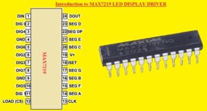
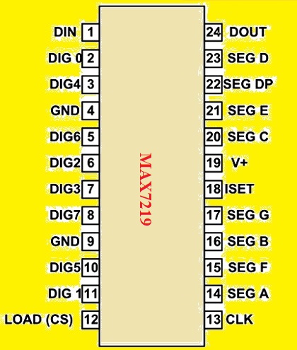
MAX7219 Pinout of MAX7219
- The main pinout of the MAX7219 LED driver are discussed here. It has twenty-four pinout
- Its pins are divided into different groups on the basis of operation
COMMON CATHODE OF DISPLAY SEGMENTS
- DIG1 is common gerund point for DGIT1 segments
- DIG2 is common gerund point for DGIT2 segments
- DIG3 is common gerund point for DGIT3 segments
- DIG4 is common gerund point for DGIT4 segments
- DIG5 is common gerund point for DGIT5 segments
- DIG6 is common ground point for DGIT6 segments
- DIG7 is common ground point for DGIT7 segments
SHARED Pins
- GND is the ground pin
- V+- here power supply connected
SHARED SEGMENT pins OF ALL EIGHT DIGITS
- SEG A is used for all Digits SEGMENT A
- SEG B is used for all Digits SEGMENT B
- SEG c is used for all Digits SEGMENT C
- SEG D is used for all Digits SEGMENT D
- SEG E is used for all Digits SEGMENT E
- SEG F is used for all Digits SEGMENT F
- SEG G is used for all Digits SEGMENT G
- SEG DP is used for all Digits SEGMENT DOT
Functional Pinout
- DIN is serail data input pin configuriaon
- LOAD is chip select or data shift pin
- CLK is clock pinout
- DOUT is the pin used to link 2nd chip in a series combination
- ISET is the current output adjust pin
MAX7219 IC USes
- It is used to control a large number of displays by connecting larger chips in a series of combination
- It is used with 7 segment display and has the ability to control eight digits
- It has a feature to link sixty-four LEDs through three pins
- It reduces the input and output pins of the controller
- Used for serial to parallel data conversion
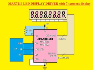
How to connect MAX7219 LED DISPLAY DRIVER to 7-segment display
- In the below figure, you can see the MAX7219 LED display driver connection with seven segment display

MAX7219 LED DISPLAY DRIVER Working
- This component operation is like a shift register. Through this module, at the start data is sent in serial communication and after that, all data is sent at once. There is a CS pin used to shift serial data transmission to output.
- DIN pin used for data sending. Data is sent in form of bits by adjusting the clock of the chip for every bit
- It stores serial data in the register till all data reach. After completion of data sending, we adjust the CS pin to shift all data stored in the register to output.
- The data in output is the form through setting DIG0-7 and pins SEG0-7 high or low.
- This high or low signal helps to on and off the single LED existing in the display
- Two methods are used for programming this led driver first one is to use datasheet instructions for data transmission serial way. The second is the use of software
MAX7219 LED DISPLAY DRIVER Applications
- The main applications are explained below
- It used in digital electronics
- Different types of networking circuits have this module for LED control
- It used in memory boards
- Usd in digital circuits
- Used in servers to indicate data transmission
- It also works as a shift operator
- Calibrating devices have this module
That is all about the HOW TO USE LED DISPLAY DRIVERS all data has been explained. If you want to know something new wait for the new tutorial


