 Hello, friends welcome to new post. In this post we will have a detailed look at Introduction to Autotransformer. It is a type of transformer that consists of single windings. It named as auto to the usage of one winding unlike to other types of transformers. In this transformer single windings operate as primary as well secondary. At the windings, there is 3 taps where electric connection are done. Since there is the use of single windings that operates as primary as well secondary so it reduces the physical dimension with that construction cost of the transformer.
There is one drawback of this single windings operating as two there is no physical separation among these two. But its benefits are more like it has less value of leakage reactance less power losses less value of excitation current, In this post we discuss its construction working application and some other related parameters. So let’s get started with Introduction to Autotransformer.
Introduction to Autotransformer
- In some electrical systems, there is need of a change in voltage at a small level. For instance, it can be compulsory to rise the voltage value from one ten volts to one twenty volts or 13.2 to 13.8-kilo volt.
- These small level variations can be cause voltage loss that exists in the system. In these conditions, it is costly to do the winding of the transformer having 2 windings.
- So there is a need of the certain type of transformer that known as an autotransformer.
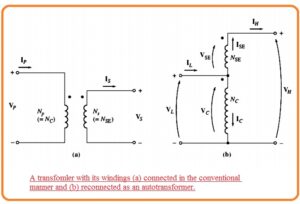
- The circuit diagram of step-up autotransformer can see in the below figure.
- In the circuit denoted as a 2 windings of the transformer can see like normal transformer. In other circuitry denoted as b the ist coil is linked in addition structure to other winding.
- So the relation among the voltage at ist winding and voltage at the 2nd windings is provided through the turn ratio of the transformer.
- Though the voltage at the output of the transformer is the summation of voltage at the ist windings and voltage at the 2nd winding.
- The ist winding is known as a common coil since voltge about this windings exist at two sides of transformer.
- The small size winding is known as series winding since it is attached in series combination to the common winding.
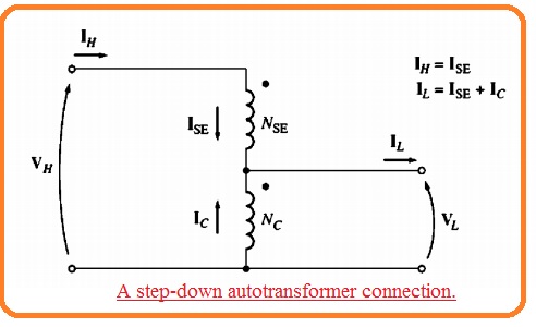
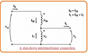
- The figure of step-down autotransformer can be seen here.
- the voltage at the input is the addition of voltage at series windings and the common winding. and voltage at the output is voltage at the common coil.
- As transformer windings, ar linked with each other practically so another category of technique is used for this transformer than other.
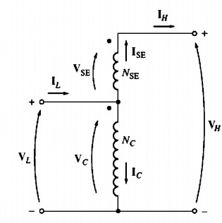
- The voltage at common winding is known as common voltage Vc and current in this windings is known as common current Ic.
- The voltage at series windings is known as the series voltage VSE and current in this winding known as series current ISE.
- Voltage and current at less voltage part of the transformer is known as VK and IL and these parameters at high voltage part are denoed as VH and Ih.
- The primary part of this transformer is at high or less voltage side. according to step up or step down configuration of the transformer.
- According to below circuit the voltage and current in winding are given through this expression.
Vc//VSE= Nc /NSE
Nc I c = NSE IsE
- The voltage in the windings are configured to the voltage given as.
VL=Vc
VH = VC + VSE
- The current in the windings is correspondent to the current according to this equation.
IL= lC+ lsE
IH = ISE
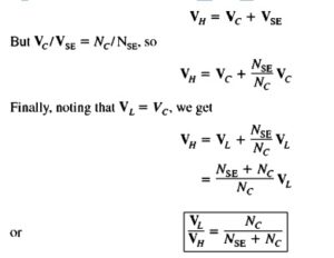
Voltage and Current Relationships Autotransformer
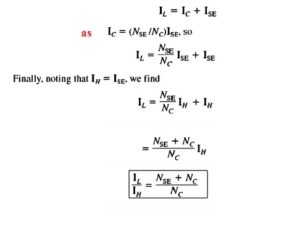
- It simple to get the relationship among the VH and VL. The voltage at high winding of autotransformer is mentioned here.
- The current relation among the 2 windings of the transformer is solved here.
Autotransformers Apparent Power
- It is great to see that net power moving from primary to secondary not goes to these windings.
- In result, if the conventional transformer is linked as an autotransformer so it can bear large power than it was handle in normal operation.
- To get this idea see above figure.
- Note that input apparent power to the autotransformer is here.
Sin = VLIL
- Output apparent power is given here.
Sout=VHIH
Sin=Sout=Sio
- Here Sio explained the input and output apparent power of transformer.
- Though the apparent power in the transformer is given here.
Sw=VcIC=VSE=ISE
- The relation among the power moving to the primary of transformer and power in the transformer real wining given here.
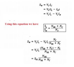
- So the ratio for apparent power in primary and secondary windings of autotransformer to apparent power given here.

- This expression says the apparent power benefits of an autotransformer than a normal transformer.
- Here Sio is apparent power moving to the primary winding and coming out from the secondary of the transformer and Sw is apparent power moving through transformer winding.
- Here if the small size of series winding larger the benefit.
Autotransformer Internal Impedance
- There is one drawback of this transformer than a conventional transformer. That these transformer linked in the normal way the effective per unit impedance of a transformer is less than factor which is equal to the inverse of power benefit of autotransformer points linking.
- The decreased inner impedance of autotransformer correspondent to the conventional 2 winding transformers is an issue in certain applications where the series impedance is required to restrict current movement in power system error like a short circuit.
- The factor of small inner impedance offered through an autotransformer should be accounted in the installation of the autotransformer.
That is a detailed post about autotransformer if you have any further query ask in a comment Thanks for reading have a nice day.

