 Hello fellows, I hope you all are doing great. In today’s tutorial, we will have a look at How to Measure Frequency Response of Amplifier. In previous tutorials, we discussed the detailed about low-frequency response, high-frequency response, total response amplifier, and frequency response of multistage amplifier. Now we discuss the measurement of frequency response. There are 2 main techniques for measurement of the frequency response of an amplifier.
These techniques are used for both BJT and FET amplifier but in this post, we will discuss for BJT amplifier. From these methods, we can also find the bandwidth. So let’s get started with How to Measure the frequency response of an amplifier.
How to Measure Frequency Response of Amplifier
Frequency/Amplitude Calculation
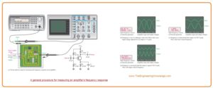
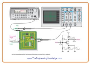
- In figure denoted as a’ the test arrangement for amplifier, circuitry board is shown.
- The diagram for the circuitry board is also shown. The amplifier circuitry is operated with the ac voltage source attached to the input and output.
- In figure denoted as b the input frequency value is set at the midrange value and amplitude is set to an output signal reference.
- This output voltage reference level for midrange must be adjusted at the easiest value in the linear operation of the amplifier.
- For instance one hundred millivolts, one volt, ten volts, etc.
- In this condition adjust the output signal to a peak value of one volt.
- Then decreases the input voltage frequency till the peak value of output loss to 0.707 volts.
- At decreased frequency, the amplitude of input voltage should be kept constant.
- Modification can be compulsory since variation in the loading of voltage source with frequency.
- When the output value is 0.707 Volts, the frequency is calculated, and you must have a value of fcl as shown in figure denoted as c’.
- After that input frequency is rises backing up the midrange and away it till the peak value of the output voltage again losses to 0.707 volts.
- Again note that the amplitude of input should have constant value when frequency increases.
- If the output voltage is 0.707 volts the frequency is calculated, and we have value of fcu it is shown in figure denoted as d’.
- By these 2 frequency calculations we can find the bandwidth by this given formula.
BW = fcu – fcl
Step-Response Measurement
- The lower and upper critical frequency values of an amplifier can find with the use of step response technique by giving voltage step to the input of amplifier circuitry and calculating the rise and fall time of resultant output voltage.
- The basic configuration is shown in the below figure. It uses that pulse output of the function producer is set.
- The input step is produced with the rising edge of a pulse which has a large time interval than the rise and fall time to be calculated.
- The rise time of input pulse should be high speed as compared to the rise time we calculate from the amplifier.
High-Frequency Calculation
- When step input is given the high frequency of amplifier RC circuitry stops the output from replying instantly to the step input.
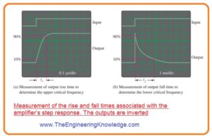
- As a consequence, the output voltage has a rise time (tr) related with it, shown in figure denoted as a’.
- The rise time is in reverse relation with the upper critical frequency (fcu) of an amplifier.
- As fcu decreases the rise time of output increases.
- The display of oscilloscope explains how rise time is calculated from a ten percent amplitude point to a ninety percent amplitude point.
- The scope should be adjusted on a small time base so the comparatively small interval of the rise time can be exactly detected.
- When this calculation is done fcu can be measured with this given formula.
fcu= 0.35/ tr
Low-Frequency Measurement
- To measure the lower critical frequency ( fcl) of the amplifier, the step input should be of adequately lengthy duration to detect the complete charging time of the low-frequency RC circuitry that cause the “sloping” of the output and that is denoted as fall time (tf). It explained in figure denoted as b’.
- There is a inverse relation between less critical frequency with the fall time of amplifier.
- As fcl increases the fall time of output goes to less.
- The oscilloscope display explains how the fall time calculated from ninety percent point to ten percent point.
- The oscilloscope should be set for large time base so the full interval of fall time can be detected.
- After doing these calculations fcl can be found with the given formula.
fcl= 0.35/ tf
That is a detailed post about How to Measure Frequency Response of Amplifier if you have any query ask in comments. Thanks for reading.


