 Hello fellows, I hope you all are doing great. In today’s tutorial, we will have a look at Analyze Multistage Amplifiers Frequency Response. In previous tutorials about low frequency response, high-frequency response, and total frequency response amplifier we discussed that the voltage gain of a single-stage amplifier varies with the variation in frequency.
If 2 or more than two stages are joined to make a multistage amplifier the overall response of frequency is found by the frequency response of every stage according to the relation of critical frequency values. In today’s post, we will have a detailed look at frequency response of the multistage amplifier and related parameters. So let’s get started with Analyze multistage amplifiers frequency response.
Multistage Amplifiers Frequency Response
- When amplifier stages are linked to make multistage amplifier the dominant frequency response is found with the response of a single stage.
- There are two conditions to take into consideration.
- There is a different value of lower and upper critical frequency for every stage.
- Every stage has the dominant same value of lower and upper critical frequency values.
Different Critical Frequency Value
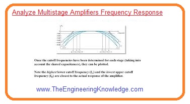
- In ideal case when the dominant lower critical frequency fcl(dom) value of every amplifier stage is not similar to the lower critical frequency and equals to the dominant critical frequency of the stage with the highest fcl(dom).
- In ideal condition when the dominant upper critical frequency fcu(dom), of every amplifier stage is not similar to the other stages the overall dominant upper critical frequency is equal to the critical frequency, and dominant critical frequency off stage is equal to the lowest fcu(dom).
- In practice the critical frequency interacts with each other therefore these measured values must be taken into consideration that is beneficial to troubleshoot the response.
- When the highest correctness is needed a computer simulation is a good option.
Overall Bandwidth
- The bandwidth of the multistage amplifier is the difference between the overall dominant lower critical frequency and overall higher critical frequency values.
BW = f’ cu(dom) – f’cl(dom)
Equal Critical Frequency Values
- If every amplifier stage in a multistage configuration has an equal dominant critical frequency, you can note that the overall dominant critical frequency is equal to the critical frequency of every stage.
- When each amplifier stage in a multistage arrangement has equal dominant critical frequencies, you may think that the overall dominant critical frequency is equal to the critical frequency of each stage.
- However, when the dominant lower critical frequency values of each multistage amplifier have the same value, the overall dominant lower critical frequency rises with the factor 1/√(21/n-1), as shown by the formula given below.
f’ cl(dom) = fcl(dom)/√(21/n-1)
- When the dominant upper critical frequency values of every stage are similar, the overall dominant frequency is decreased by the factor of √(21/n-1).
f’cu(dom) = fcu(dom) √(21/n-1)
Computer Simulation for Multistage Amplifiers
- For a multistage amplifier, the complete calculations of the frequency response can be made simple through computer simulation.
- There are numerous collaborations in every stage and other collaborations among the stages that affect the overall frequency response.
- For greater correctness, use computer simulation.
What is the frequency response of an amplifier?
- The frequency response of amplifiers is defined as the frequency range where amplifiers operate with low effects of capacitors and inner capacitance of the device. That frequency value is called midrange. The Bode plot shows the frequency response of the amplifier.
What is the frequency response of an RC-coupled multistage amplifier?
- • The frequency response of an RC-coupled amplifier is linear for the mid-frequency range of 50 Hz to 20 kHz.
- The voltage gain losses at low (<50) and high (20 kHz) frequencies
What is a multistage amplifier?
- The multistate amplifier circuit comes with two or more single-stage amplifiers configured with each other. A single-stage amplifier comes with one transistor or active device.
What is the advantage of using a high-frequency response of a multistage amplifier?
- The circuit comes with a single transistor amplifier that does not have good bandwidth or gain value. For minimizing this factor, there are different amplification stages connected. The high-frequency response of multistage amplifiers is used for high gain and also for high bandwidth.
What are the disadvantages of a multistage amplifier?
- Low voltage and power gain are disadvantages since effective load resistance is reduced since the input of each state shows low resistance at the next stage. Moisture sensitivity causes noises as time elapses.
What is the difference between cascade and cascode amplifiers?
- Cascade connections just couple outputs with inputs, giving high gain. Cascode connection increases input impedance and painting single-stage gain. Darlington connections come with high current gain close to a multiple of individual transistor gains.
That is all about Analyze Multistage Amplifiers Frequency Response if you have any further query ask in comments. Thanks for reading.


Hello, I have a very big problem that no matter where I search online I seem not to find and answer to the matter and you seem like a professional so I’ll task you, hope you May have the answer.
For the exam of Electronics that I have to do we have to bring a self made multistage amplifier with what ever characteristic, and as example he show us a 2 stage amplifier with JFET as common source (with retroaction) and common drain ac coupled.
All fine until the low frequency cut off, we have to give the value of the resistance and capacitance depennino on whatever Signal we are expecting to amplify.
He says let’s fix the frequency of all the capacitor, so all 4, Cin, Cout, bypass C and coupling C, at 5 hz so the total cut off frequncy will be at circa 23 hz, without explaing why. Even using the formula that you present here I get a result of 11.5 hz replacing the n with 4 and the f with 5. Looking at the project with LtSpice it true that it’s 23/24 hxz but why?