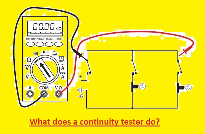
The continuity test is a device that is used to test the existing electrical path between two points for current flow. Before doing the test circuit where test has to be performed must be off from supply. The tester comes with an indicator in a series of power source-like batteries, with two test leads. If there is a complete circuit between testing leads then the indicator will be operated. The indicator can be a buzzer or an electrical light. This indication means the buzzing of the circuit means the continuity test is performing. In some multimeters, audile continuity buzzers are configured and the setting used for continuity is configured with an ohmmeter setting. The famous desing comes with a tester combination with a standard flashlight. The phone connector or jack plug at the back side of the unit helps to set testing leads to connecting fast conversion of two uses.
In applications where continuity test is performed on the high value of resistance circuits or where conductors and sensitive components are affected due to high current where low voltage and current are used. There are operational amplifiers and a watch battery used to operate LED as an indicator.
At starting time normal continuity tests do not provide accurate results such as vibration-induced issues in vehicle wiring can make it difficult to find short or open circuits. In these circuits latching continuity tester is used. The complicated devices detect open and short circuits also steady-state conditions. These devices come with fast-acting electronic switches making gated stable oscillators that sens and lock indicators in less than a millisecond.
Introduction to Continuity test
The continuity test is performed in an electronic circuit to check that the current is flowing. The test is done by providing a small voltage across the circuit. If the curent does not flow due to broken conductors, damaged components, or high resistance it means the circuit is open. A multimeter is used to measure current continuity and certain types of continuity testers are used or some basic devices that glow the bulb when current passes through them.
Why is Continuity Testing Done?
The main purpose of the continuity test is to check that CPC forms a continuous path about the circuit under the testing process. This test is an important testing process to find any damaged component of the circuit. It also helps to find the accuracy of the soldering process, find the high resistance that affects the current flow, and find electrical wiring broken between two points.
This test is also helpful for verifying the connection of the circuit. This test is also used to detect cold solder connections and issues with wires and cables. Normally handheld multimeter with a dual probe is used for this purpose. With that, this testing process is used to check the connection between pads and traces of PCB boards.
Read also:What is a Cold Solder Joint and How Can You Prevent it?
What During Continuity Testing?
The very common and simple method to do continuity tests is the use of a resistance tester. Since the resistance of the conductor between two endpoints is normally very less about less than a hundred ohms. Continuity tests come with two probes connected to a small battery and when touched lead with a circuit meter must have zero resistance, or if some special taste that must have a light on. If there’s a digital multimeter that will sound beep.
Continuity of protective conductors with main and supplementary equipotential bonding. Each protective conductor with circuit protective conductor, eating conductor, and supplement bonding conductors must be tested to check all bonding conductors connected with supply earth. Test are between main erthing points and end points of every bonding conductor.
Continuity symbol
The symbol for continuity can be different based on the brand and the model. Normally continuity mode comes with a diode symbol. tha is a triangle with a line on the right side. It also has a symbol that is like the soundwaves
How to do Continuity Testing?
Measuring Continuity in Electrical Devices:
This technique is used to test continuity in easy ways to find a theater switch whose outlet has inner damage. With the use of a multimer set it at continuity function or choose a midrange resistance setting, in ohms. Follow these steps to perform the test
- First of all off the power supply to perform test. Check that no current is passing with the use of a noncontact circuit tester.
- Check the test by putting leads with each other and make sure that devices light up, produce sound, or have zero resistance.
- Connect one lead with one of the hot points of the device and identified with the use of a brass screw.
- Connect other leads on any other terminal letting green ground point. If the test glows or has zero resistance, it means current can pass between these points, and in some conditions device is working well. If the device is switched tests must be off and on when we flip the switch.
This method is used to check the working of switches, fuses, and thermostats. Must make sure that power is off then touch leads with terminals.
What tool is used to test the continuity of wiring?
Applications of Continuity Testing
The continuity test performed with the use of a digital multimeter is best for testing switches, fuses, electrical connections, conductors, and another electronic components. such as an accurate working fuse must have continuity.


