Hi, readers welcome to the new post. In this post, we will learn Arduino Mega2560. Arduino Mega 2560 is part of microcontrollers and comes with ATmega2560 configuration. It comes with 54 pinouts that are used for the connection of external devices. These inputs are digital and 16 are analog pins.
Here we cover its basic pins working and other related parameters and know-how that can be practically used. So let’s get started.
What is Arduino Mega 2560?
- The Arduino Mega 2560 comes with a total of 54 inputs/outputs out of which 16 are analog inputs, and it has 4 UARTs and a 16 Mhz crystal oscillator.
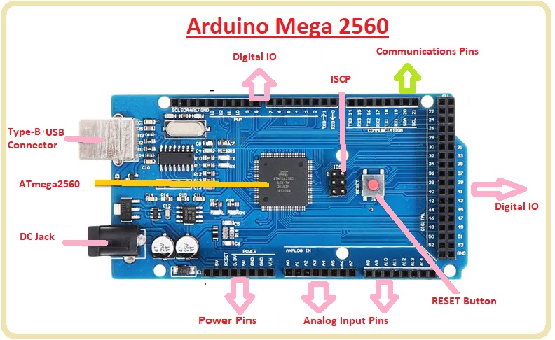
- It also comes with a USB connection, ICSP header, reset button, and power jack.
- It comes with all the features that are important for any type of microcontroller. Just make its connection with a USB cable or power with an AC to DC adapter.
- It also supported the Arduino Duemilanove or Diecimila. This board is like the Arduino UNO board and has high power as compared to Arduino UNOT.
- It is a new version of Arduino Mega called ATMega2560. Its memory space is larger than other boards.
- It is different from other boards that were used before since they do not have FTDI USB to serial driver
Arduino Due vs Arduino Mega
| Technical Specifications | Arduino Due | Arduino Mega |
| . Microcontroller: | Atmel AT91SAM3X8E ARM Cortex-M3 CPU running at 84 MHz. | ATmega2560 |
| Operating Voltage: | 3.3V. | 5V |
| Input Voltage (recommended): | 7-12 volts. | 7-12V |
| Input Voltage (limits): | 6-20 volts. | 6-20V |
| Digital I/O Pins: | 54 | 54 (of which 15 provide PWM output) |
| Analog Input Pins: | 12 | 16 |
| Analog Output Pins: | 2 | 16 analog inputs |
| DC Output Current | 130 mA. | 20 mA |
| DC Current for 3.3V Pin | 800 mA. | 50 mA |
| Flash Memory: | 512 KB | 256 KB |
| SRAM: | 96 KB | 8 KB |
| Clock Speed: | 84 MHz. | 16 MHz |
| Communication Interfaces: | UART: 4 (Serial Communication) SPI: 1 (Serial Peripheral Interface) I2C: 1 (Inter-Integrated Circuit) CAN: 1 (Controller Area Network) USB: 2 (Host and Device). | UART: 4 (hardware serial ports) I2C: 1 SPI: 1 CAN: None USB: Type-B connector |
| Operating Temperature: | -40°C to +85°C. | –40°C to 85°C |
Arduino Mega 2560 Features
- It is an ATmega2560-based microcontroller and the operating voltatge is about five volts.
- Its recommended input voltage is 7 to 12 volts
- The input voltage range is about 6 to 20 volts
- Its digital input/outputs are 54 and 15 PWM output
- It comes with an analog 16-input
- DC for a single input or output pin is 40 mA
- DC value for 3.3V pin is 50mA
- Its flash memory is about256 KB with static RAM is 8 KB
- Its EEPROM is 4KB and its clock speed is about 16 MHz
- USB Host Chip type is MAX3421E
- Its dimensions are Length 101.52 mm and Width is 53.3 mm
- Its Board Weight is 36 g
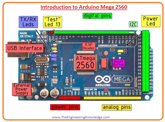
Pinout of Arduino Mega 2560
- The pinouts of Arduino Mega 2560 are described here with the details.
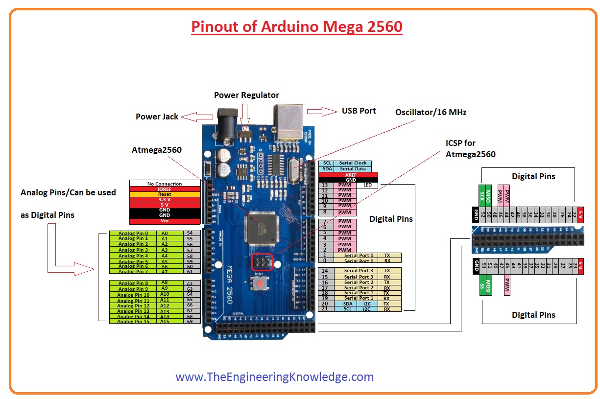
- It has 54 digital pinouts that are used for input and output pins.
- 15 Pins are used for PWM or ( pulse width modulation )
- There are 16 analog input pins and ground pins
- It has 3.3 pins where 3.3 voltage is applied.
- It has one reset button
- It comes with 4 USART pins which are hardware serial ports that generate about high speed for setting up communication.
- There are ISP 6 programming pins on this board.
- It has a crystal oscillator with 16 MHz
- It comes with a USB cable port and is used for transferring and connecting code with a computer board.
- ICSP header employed for programming board and upload code from the computer.
- It comes with a power jack
SPI Communication
- . 4 pins are used for SPI communication that are MISO (50), MOSI (51), SCK (52), and SS (53).
Dimensions
- The Arduino Mega 2560 board has dimensions of 101.6 mm in length and 53.34 mm in width. It is larger as compared to other boards. The power jack and USB port are slightly beyond these dimensions.
Arduino Mega 2560 Programming
- Arduino Mega 2560 is programmed with the use of Arduino IDE that is compatible with C programming language. The code is written in IDE and uploaded to the Arduino board with the use of a USB cable.
- The Arduino mega baord comes with a bootloader that reduces the use of an external burner for programming the Arduino board. The bootloader is used for communication with the use of the STK500 protocol.
| Pin # | Pin Name | Function |
| 1 | TX0 | It is a serial data transmission pinout (Serial 0) |
| 2 | RX0 | Hre serial data received |
| 3 | XCK0 | It is outer clock input serial communication performed) |
| 4 | PWM2 | Here PWM output taken |
| 5 | PWM3 | It is also the pulse width modulation output |
| 6 | PWM4 | pulse width modulation output pin |
| 7 | PWM5 | pulse width modulation output pin |
| 8 | PWM6 | pulse width modulation output pin |
| 9 | PWM7 | pulse width modulation output pin |
| 10 | INT4 | Here interrupt four inputs provided |
| 11 | INT5 | That is five interrupt input |
| 12 | TMS | Through these pins JTAG test mode selected |
| 13 | TCK | JTAG test clock signal provided |
| 14 | TDO | JTAG testing data is taken out |
| 15 | TDI | JTAG data is provided |
| 16 | TOSC1 | It is a time oscillator input pin |
| 17 | TOSC2 | It is the second Timer oscillator input pin |
| 18 | ADC0 | Here input is provided to ADC |
| 19 | ADC1 | It is ADC i/p pinout |
| 20 | ADC2 | ADC i/p pinout |
| 21 | ADC3 | ADC i/p pinout |
| 22 | ADC4 | ADC i/p pinout |
| 23 | ADC5 | ADC i/p pinout |
| 24 | ADC6 | ADC i/p pinout |
| 25 | ADC7 | ADC i/p pinout |
| 26 | PC0 | It is a digital I/O Pin |
| 27 | PC1 | It is a digital I/O Pin |
| 28 | PC2 | It is a digital I/O Pin |
| 29 | PC3 | It is a digital I/O Pin |
| 30 | PC4 | It is digital I/O Pin |
| 31 | PC5 | It is digital I/O Pin |
| 32 | PC6 | It is a digital I/O Pin |
| 33 | PC7 | It’s a Digital I/O terminal |
| 34 | PD0 | It’s Digital I/O terminal |
| 35 | PD1 | It’s Digital I/O terminal |
| 36 | PD2 | It’s Digital I/O terminal |
| 37 | PD3 | It’s Digital I/O terminal |
| 38 | PD4 | It’s Digital I/O terminal |
| 39 | PD5 | It’s Digital I/O terminal |
| 40 | PD6 | It’s Digital I/O terminal |
| 41 | PD7 | It’s Digital I/O terminal |
| 42 | PE0 | It’s Digital I/O terminal |
| 43 | PE1 | It’s Digital I/O terminal |
| 44 | PE2 | It’s Digital I/O terminal |
| 45 | PE3 | It’s Digital I/O terminal |
| 46 | PE4 | It’s Digital I/O terminal |
| 47 | PE5 | It’s Digital I/O terminal |
| 48 | PE6 | It’s Digital I/O terminal |
| 49 | PE7 | It’s Digital I/O terminal |
| 50 | PB0 | It’s Digital I/O terminal |
| 51 | PB1 | It’s Digital I/O terminal |
| 52 | PB2 | It’s Digital I/O terminal |
| 53 | PB3 | It’s Digital I/O terminal |
| 54 | PB4 | It’s Digital I/O terminal |
Arduino Mega 2560 vs Arduino Mega 2560 Rev3
Arduino Mega 2560
- It comes with ATmega2560 controller
- Operating voltages are 5 volts.
- Input voltatge is 7 to 12 volts
- 54 input with 15 PWM
- It has 16 analog pins
- DC value is 20 milliampers.
- DC for 3.3 pins is 50millimapers.
- 256 KB memory Flash memory
- Eight kilobyte of SRAM and Four kilobyte EEPROM
- 101.52-millimeter length and 53.3-millimeter width
- 37-gram weight
- USB to Serial is FTDI
Arduino Mega 2560 Rev3
- It comes with an ATmega2560 controller
- Operating voltages are 5 volts and input voltage value is 7 to 12 volts
- 54 pinouts and 15 out of them are PWM
- 16 analog pins
- 20 Millimpaers DC
- 50 Millimpaers for DC for 3.3 volts pins
- 256KB flash memory
- EIght kilobyte SRAM and four kilobyte EEPROM
- The clock speed is sixteen megahertz
- 101.52 millimeters in length and width 53.3 millimeters and weight is 37 grams
- USB to Serial is ATmega16U2

Arduino Uno vs. Mega vs. Micro
| Features | Arduino Uno | Arduino Mega | Arduino Micro |
| Microcontroller Type | ATmega328P-8-bit | ATmega2560 | ATmega32U4 |
| Operating Voltage | 5Volt | 5Volt | 5Volt |
| Suggested Voltage | 7-12Volt | 7-12Volt | 7-12Volt |
| Flash Memory | 32 KB | 256 KB | 32 KB |
| SRAM | 2 KB | 8 KB | 2.5 KB |
| EEPROM | 1 KB | 4 KB | 1 KB |
| Frequency(Crystal Oscillator) | 16 MHz | 16 MHz | 16 MHz |
| Analog Input Pins | 6 (A0 – A5) | 16 | 12 |
| Digital I/O Pins | 14 (6 gives PWM output) | 54 (14 gives PWM output) | 20 (7 gives PWM output) |
| DC Current on 3.3V Pin | 50 mA | 50 mA | 50 mA |
| DC Current on I/O Pins | 40 mA | 40 mA | 40 mA |
VOLTAGE- CURRENT Features Arduino Mega 2560
- Operating voltage: 5 V
- DC Current per input/output pin: 20mA
- Input Voltage 7-12 V (recommended)
- Input Voltage 6-20 V
- DC Current for 3.3 V pin: 50mA
Faqs
How to run Arduino Mega 2560?
- Make the connection of Arduino 2560 with a computer through the use of a USB cable. Open Arduino IDE and choose the accurate board type and serial port in the Tools menu. For Arduino Mega2560, choose, Arduino/Genuino Mega or Mega 2560 since the board type and the accurate serial port of the devices
What is the RAM of Arduino Mega 2560?
- ATmega2560 comes with 256 KB flash memory for code storing, 8 KB of SRAM, and 4KB EEPROM.
What is the input voltage for Arduino Mega 2560?
- Its operating voltage is 6 to 20 volts and provides less than 7 Volts and a 5V pin can provide less than 5V and the board gets unstable.
- If more than 12 volts and voltage regulator overheats and also gets damaged. The recommended voltage range is 7 to 12 volts.
What is the function of ATmega2560?
- The device gets a throughput of 16MIPS at 16 MHz and works in the range 4.5-5.5 volts. The use of high-power instructions in single clock cycle devices gets a throughput of 1 MIPS per MHz,
What is the Arduino Mega 2560 used for?
- Arduino MEGA 2560 is made for different projects that need a larger number of input/output lines more memory and higher RAM. It has 54 digital input output pins, so used for 3D printers and robotics projects.
What is the difference between Arduino Mega 2560 and due?
- Arduino Due is a 32-bit ARm cortex M3 processor with higher performance than Mega’s 8-bit ATmega2560 for speed and power. The due and mega boards come with different operating voltages such as 3.3V and 5V
Is Mega faster than Uno?
- The Mega and UNO come with a clock speed of 16MHZ and memory and storage space is not the same. Mega comes with flash memory of 256KB and UNO is 32kB. If the code is higher best to use Mega since has a larger memory. Static RAM is used for Arduino systems.