 Hi, readers, I hope you all are doing great. In today’s post, we will have a detailed look at Types of Active Band-Pass Filters. The bandpass filter configuration has the ability to pass types of frequency through a lower frequency limit and upper-frequency limit and do rejection for all other frequency ranges existing beyond this range.
The bandpass response can be taken as an overlapping of less frequency response curvatures and large frequency response curves. So let’s get started with Types of Active Band-Pass Filters.
What is Cascaded Low-Pass and High-Pass Filters
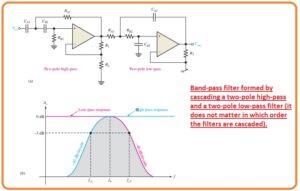
- The method for implementation of the bandpass filter is cascaded configuration of a high pass filter and low pass filter configuration as you can see in the below figure. With that critical frequency is parted accurately.
- Every of the filter is can be seen in a Sallen Key Butterworth arrangement therefore the roll-off rates are denoted in the composited response of curvature. shown in figure denoted as b.
- The critical frequency of every filter is selected therefore the response curve gets mixed or overlapped accurately as shown.
- The critical frequency of the high pass filter should be accurately less than the low pass stage.
- This filter configuration is normally restricted to different bandwidth application that has wide ranges.
- The less frequency of passband is the critical frequency of the high pass filter. The upper frequency is the critical frequency of less pass filter configuration.
- In dieal the center frequency of passband is the geometric mean of fc1 and fc2.
- The given below formula denotes the 3 frequency of bandpass filter as shown in the below figure.
fc1=1/2Π√RA1RB1CA1CB1
fc2=1/2Π√RA2RB2CA2CB2
f0 =√fc1 fc2
- So if the equal value of elements are used in every filter the critical frequency equation becomes
fc = 1/(2ΠRC)
What is Multiple-Feedback Band-Pass Filter
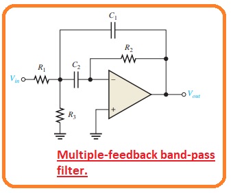
- Other category of filter arrangement is can be seen in the below figure, in this figure the multiple feedback bandpass filter is shown.
- The 2 feedback paths moving through the resistance R2 and capacitor C1.
- The elements Resistance R1 and C1 offer the low pass response and resistance R2 and capacitor C2 offer the high pass response.
- The extreme gain value is A0, which exists at the center frequency. Q values of lesser than the ten generally exist in this category of the filter.
- The relation for the mid-frequency is created as regarding the resistance R1 and R3 indicates in parallel combination are shown from the capacitor C1.
if C1 = C2 = C
f0 =1/√(R1ΙΙR3)R2C∧2=1/2Πc√(R1ΙΙR3)R2
=(1/2πC)√1/R2(R1ΙΙR3)
=(1/2πC)√(1/R2)(1/R1R3/R1 + R3)
f0=1/2πC√(R1+R3)/R1R2R3
- The value of the capacitor is can be selected and then the 3 resistance parameters are measured to get required parameters for fo, BW, and A0.
- As we know that the Q can be found from the Q = f0/BW.
- The resistance value can be measured with the use of these relations.
R1 =Q/2πf0CA0
R2 =Q/πf0C
R3 =Q/2πf0C(2Q∧2 – A0)
- For the creation of the gain values, we solve Q in the expression or resistance R1 and R2.
Q =2πf0A0CR1
Q = πf0CR2
so
2πpf0A0CR1 =πf0CR2
2A0R1 = R2
A0=R2/2R1
What is State-Variable Filter
- The state variable is also called universal active filter is generally used for bandpass projects applications.
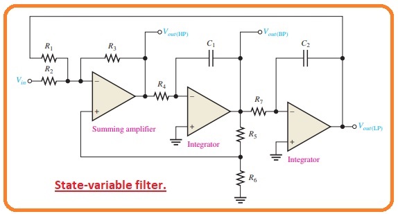
- It can be seen in the below figure that it comprises a summing amplifier and 2 operational amplifier integrators which are attached in cascaded configuration to create 2nd order filter configuration.
- though it is used as a bandpass filter the state variable arrangement also gives the low pass and high pass outputs.
- The mid-frequency is adjusted by the RC circuitry in these to integrators circuits.
- When it operates as a bandpass filter the critical frequency of the integrators are generally has similar values.
Basic working
- At input frequencies less then the fc the input signal moves in the summing amplifier and integrator and sends back with phase changing.
- SO the feedback signal and input signal cancel out for all frequency values less than fc.
- As the low pass response of the integrator rolls off the feedback signal eliminates so permitting the input to move through the bandpass output.
- Over the fc the low pass response diminishes so stoping the input signal from moving through the integrators.
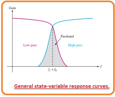
- As a quencequence the bandpass filter results has a sharp peak at fc, as shown in the below figure.
- The stable Qs to the one hundred can get with this category filter.
- The Q is adjusted by the feedback resistance R5 and R6 according to the given relation.
Q = 1/3(R5/R6+ 1)
- The state variable filter configuration can not be transformed for low pass high pass and narrow bandpass operations at the same time.
- To transform for a low pass or high pass, Butterworth’s response DF should have a value of 1.414.
- As a Q of 0.707, we consequence.
DefineBiquad Filter
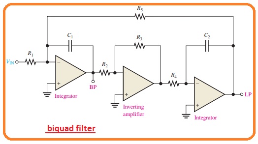
- The biquad filter is like to the state variable filter with the difference that it comprises of the integrator, with the inverting amplifier and another category of the integrator.
- Such differences in the arrangements among the biquad and stable variable filter arrangement cause in some operation difference though both permit a large value of Q.
- In a biquad filter, the bandwidth is not dependent and the Q is dependent on the critical frequency though in-state variable filter it is only the reverse the bandwidth is dependent and the Q is non-dependent on the critical frequency.
- With that biquad filter offers only bandpass and low pass output.
That is all about the Types of Active Band-Pass Filters if you have any further query ask in comments. Thanks for reading.

