 Hi, friends welcome to another interesting post. In this post, we will have a detailed look at Gain versus the frequency response of Filter. Filters generally have types according to the way that has variation in output with respect to the frequency of input voltage. The common types of active filters are low pass filter, highpass filter, band stop, and bandpass filter. The general response of every category is monitored.
In this post, we discuss these filter’s operation and describe the gain and frequency relation of these filters. So let’s get started with Describe Gain-versus-Frequency Responses of Filters.
What is Low-Pass Filter Response
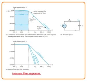
- The filter is circuitry which passes specific frequency and performs an attenuation or rejection process on these frequencies. The passband of any filter is the frequency range which is permitted to move through the filter having the least attenuation.
- The critical frequency which also known as cutoff frequency describes the end of passband and is generally defined at the location where response decrease to 70.7 percent from the passband response.
- This passband is an area known as transition region which leads to the area or region which is known as stopband.
- There is no certain location among the transition and stopband region.
- The low pass filter is such type of filter through which frequency moves from dc to fc and accurately do attenuation of another category of frequencies.
- The passband of the low pass filter is can be seen in the blue-colored area as shown in the figure.
- The response approaches to 0 at frequency away from the passband.
- This ideal response is defined as a brick wall since there is nothing to get away from this wall.
- The bandwidth of an ideal low pass filter is like to the fc.
BW=fc
- The ideal response as shown in figure denoted as a, is attainable through any practical filter.
- The real filter response relies on the number of poles the terminology used with a filter to explain the number of RC circuitry comprises in the filter.
- The main low pass filter is normally RC circuitry comprises of only one resistance and with that have a single capacitor, the output is measured about the capacitor as shown in figure denoted as b.
- The RC filter comprises of one pole and it rolls of at the away from critical frequency.
- The real response is defined by the blu line shown in figure denoted as a.
- The response is drawn in graph form on a standard log plot which is used for the filter to display the description of the curve like the gain drops.
- Note that the grain crops off gradually till the frequency has critical value, after this, the gain value decreases fastly.
- The -20dB/decade roll-off the rate for the gain of basic type of RC filter denotes that for a frequency of output will be ten percent of the input.
- This roll off rate is not a certainly good filter features since a very large value of undesired frequency values are permitted by the filter.
- The critical frequency of low pass RC filter exist when Xc =RC here
fc=1/2πRC
- As we know that the basic dc/ac output at the critical frequency is 70.7 percent of the input.
- This response is equal to the minus three dB.
- The figure denoted as c defines 3 ideal low pass response graphical respresntiaon comprises the single pole response.
- The estimations indicate that a false response to the cutoff frequency and roll of at a constant ratio after the cutoff frequency.
- Real filters do not comprise of accurately flat response up the cutoff frequency but a loss to the minus three dB this point we already discussed.
- For the production of filter which has a steep transition area, it is compulsory to connect the extra circuits to the basic filter configuration.
- The response which is steep in form than the transition area does not get through general cascading identical RC stages.
- Though through joining an operational amplifier through frequency selected feedback circuitry, the filter can be created through a roll of rates -40, -60, or larger dB/cascade.
- Filter which comprises one or more than one operational amplifier in the circuitry known as active filters.
- Such a filter can optimize the roll-off or other terms like phase response having a certain filter configuration.
What is High-Pass Filter Response
- The high pass filter response is such a type of filter that accurately do attenuation or rejection process for all types of frequency less than the fc and allows to pass the frequency over the fc.
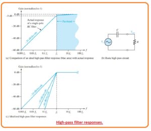
- The critical frequency is the frequency over which the output is 70.7 percent of the input as you can be seen in the below figure denoted as a.
- The ideal response that is shown in the form be below shaded region has instantaneous loss over which fc that is not easy to get.
- In an ideal case, the passband of high pass filter is all frequency over the critical frequency. The large frequency response of practical circuitry is restricted through the operational amplifier or other elements that create the filter.
- The simple RC circuitry comprises of one resistance and one capacitor can be arranged as a high pass filter by measuring the output about the resistance as you can see in figure denoted as b.
- In the case of low pass filter, the basic RC circuitry has a roll-off rate -20dB/decade as shown by the blue color region.
- With that, the critical frequency for the general highpass filter exists in case Xc = R here
Xc=1/2πfc
- figure denoted as C defines 3 ideal high pass response graphical curves comprises the general single-pole response for high pass RC circuitry.
- In the case of the lowpass filter, the estimations indicate a flat response to the cutoff frequency and roll of at a constant rate after the cutoff frequency.
- Real high pass filters do not have the accurate flate response denoted or the accurate roll of rate is can be observed.
- The response which has a steep curve than -20db/decade in the transition region is obtainable through high pass filter.
What is Band-Pass Filter Response
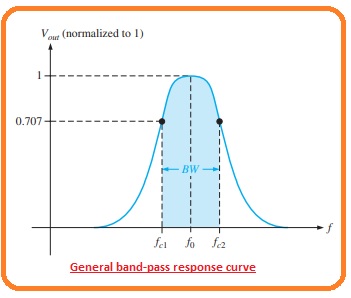
- The bandpass filter response allows to pas all types of signal existing in the band among the lower frequency limit and upper-frequency limit and necessarily do rejection for all other types of frequency which do not rely in the certain band.
- The general bad pass response curvature is can be seen be below figure.
- 15-3
- The bandwidth is described as the difference among the upper and lower critical frequencies.
BW=fc2-fc1
So friends that are all about Gain-versus-Frequency Responses of Filters if you have any further query ask in comments. Thanks for reading. Have a good day.


