Hi, readers welcome to the new lecture. Here you will learn about the Introduction to BT136 TRIAC. This triac has features to bear the four-ampere extreme current at its pinout. It is employed in digital circuits since the value of gate volts is less. The bidirectional operation can be used for AC circuits where polarity varies. Due to these features are used for microcontrollers having current values of less than six amperes.
Here we will discuss different parameters for this triac with the details. So let’s get started.
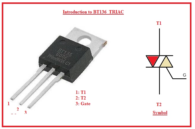
Introduction to BT136 TRIAC
- This TRIAC comes in bidirectional nature and can operate in voltage and negative polarity.
- Due to two operations polarity has features to operate in 4 quadrants.
- It is a planar passivated and sensitive gate that comes in TO-220 plastic-coated packaging.
- It is mostly preferred for to direction switches and control of phase circuits.
- It preferred for IC logic gates and some less power-triggering circuits.
BT136 Features
- The main features of BT136 are mentioned here.
- It has a casing of TO-220.
- The value of the latching current is four millimeters.
- The holding current for this device is 2.2 milliamperes
- Terminal volts is six hundred volts
- Gate trigger current is ten milliamperes
- It has sensitive nature of the gate
- It can function in all 4 quadrants
- It can restrict the high value of volts.
| Features | Details |
| Type | TRIAC |
| Repetitive Peak Off-state Voltage | 600 V |
| RMS On-State Current | 4 A |
| Gate Trigger Voltage | 1.3 V |
| Gate Trigger Current | 10 mA |
| Non-Repetitive Peak On-State Current | 25 A (at 60 Hz), 26 A (at 50 Hz) |
| Holding Current | 25 mA |
| Package Type | TO-220AB |
| Operating Junction Temperature Range | -40 to +125 °C |
| Isolation Voltage | 2500 V |
| Latching Current | 4 mA |
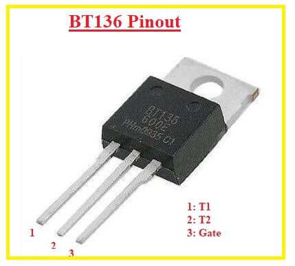
BT136 Pinout
- There are 3 pinout it has described here
- Pin 1 It is linked to the phase wire or neutral of ac supply.
- Pin 2: Here phase or neutral of AC supply linked
- Gate: It helps to operate the SCR
BT136 Operation Technique
- As we discussed, TRAIC is used for AC circuits; there must be some precautions taken into account before use.
- There must be a used snubber with the triac to avoid the rate effect that is created when high volts come at the terminal of the triac suddenly.
- They must stop the backlash effect that is created due to the capacitance occurrence between the MT1 and MT2 pins. To minimize this effect, resistance in a series combination is used.
- For AC volts control, the zero-crossing technique is employed.
- To minimize the harmonics and EMI, there must be separation from digital electronics.
- To minimize the backward flow of current in the case of inductive loads, there must be alternative discharge paths used.
BT136 Applications
- Its common applications are discussed here.
- It is used for the control of AC and DC power circuits.
- In processors used for regulation of AC output’s
- It is used in noise-coupling circuits.
- It is used as a dimmer in lighting circuits.
- Speed of AC motors, such as induction motors and synchronous motors, is done through these devices.
BT136 600E TRIAC Circuit
- BT136 600E TRIAC used for AC power switching circuits that is compatible with 600V and 4 amperes. It provides back-to-back thyristor configurations.
- This TRIAC, when connected with an optocoupler such as the asMOC3021, regulates high-voltage devices in the range of 230 volts for bulbs and motors. Providing functions like dimming and speed control with the use of PWM.
- The main components of circuits are resistors and capacitors.
- The compatibility with high voltage and currents, BTE136 TRIAC, is used for different conditions such as at homes and industrial applications.
- It is low cost as compared to thyristor design.
- If configured with control circuits such as microcontrollers, BTE135 600E TRIAC is important.
- It is a staple for automation circuits like light dimming and fan speed regulation. This component is the main part of smart home devices and is used for power control.
- The easy configuration of BTE136 is that the optocoupler is high-speed and effective in design.
- The main use is Arduino to manipulate PWM signals, providing good light conditions that increase good saving features.

Precautions for BT136 600E TRIAC
- The creation of a TRIAC circuit that has features for handling AC voltage is done in a proper way. TRIAC circuits work in a phenomenon called Rate Effect that exists when TRIAC switches and high voltage occur at any pin and can damage TRIAC. This issue can be solved with the use of a snubber circuit.
- The other problem is that the black box effect results when accumulated capacitance between 2 pins of TRIAC, like MT1 and MT2. So TRIAC does not switch on also if voltage is given to the gate terminal. That issue can be solved with the use of a resistor in series with capacitance.
- The controlling output AC voltage for speed control, the zero-crossing method, is used. The TRIAC for switching circuits has chances for EMI interferences and harmonics, and it needed to be isolated from digital electronics.
- There is a chance of backward current if TRIAC regulates inductive loads, so an alternate discharge path is given for the surge current that flows from the load to the drain.
That is all about the BT136 triac all details has been discussed if you have any further query ask in the comments. Thanks for reading have a nice day see you in next post.