 Hello friends, I hope you all are doing great. In today’s tutorial, we will have a look at How to Troubleshoot Transistor (BJT) Circuits. Troubleshooting of circuits using transistor or BJT is a process through which we find any fault or malfunction existing in that circuit through different tests. There are different ways to find the fault in circuits in this post will discuss different techniques to troubleshoot transistor circuits.
In this post, we will have a detailed look at the troubleshooting of transistor biased circuits and perform different tests on the transistor. So let’s get started with How to Troubleshoot Transistor (BJT) Circuits.
How to Troubleshoot Transistor (BJT) Circuits
Troubleshooting a Biased Transistor
- There are numerous errors and faults that can exit in the transistor biased circuits.
- The main faults are open biased resistance, open connections, short circuit, etc.
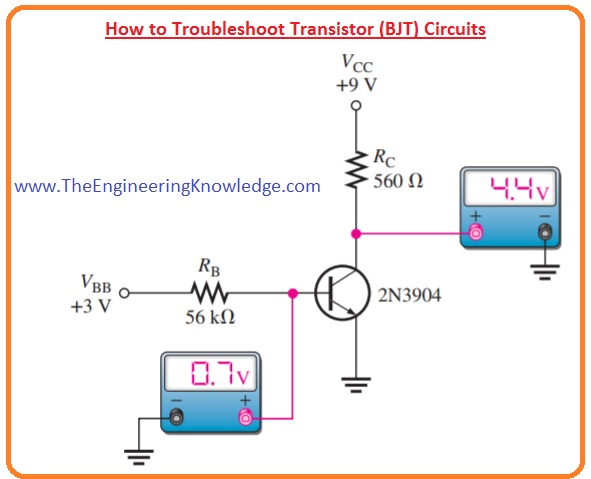
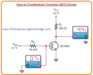
- The below figure shows the transistor bias circuitry in which all voltages are referenced with the ground terminal.
- 2 bias voltages are VBB and VCC which are three and nine volts respectively.
- The unfault values of base and collectors are shown. These voltages values are defines as.
- βDC is taken two hundred volts halfway among the least and extreme values of hFE given on the datasheet for the 2N3904 shown in the below figure.
- The different values of hFE (βDC) will result in different outputs for a given circuit.
VB = VBE = 0.7 V
IB= (VBB-0.7)/RB
=(3 V – 0.7V)/56kΩ
=2.3/56kΩ
=41.1uA
IC = βDCIB
=200(41.1 uA)
=8.2mA
VC = 9 V – ICRC
9 V – (8.2 mA)(560Ω) =4.4V
- Numerous faults can exits in the circuitry and associated indications are illustrated in below figure.
- Faulted signs are shown in the form of measured voltage which is not correct.
- If a transistor is not working accurately it is a good choice to check that VCC and ground are linked are working.
- A general check at the topmost of the collector resistance and at the collector itself will rapidly determine if VCC is existing and if the transistor is operating in normal condition or is in cutoff or saturation.
- If a transistor is in cutoff condition collector voltage is equals to the VCC and if it is in saturation collector voltage will be 0.
- Another defective calculation can be observed if there is an open circuit in the path of a collector.
- The point which is not linked to the ground is known as floating-point.
- Usually, very less and sometimes changeable voltages in the microvolts to less millivolts range are usually calculated at floating points.
Testing a Transistor with a DMM
- The digital multimeter is used as a high speed and reliable method to check transistor open or short points.
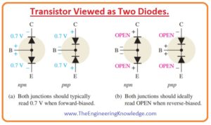
- In the below figure you can see that transistor as 2 diodes are linked for both NPN and PNP transistor.
- The base-collector junction is operating as one diode and base-emitter is like another diode.
- As we know that a fine diode will exhibit a large value of resistance for a reverse biased condition for forward bias condition.
- A faulted diode shows very less or 0 value of resistance for both forward and reverse biased states.
- A most common type of fault is an open diode. As the transistor PN junction and diodes have the same basic features.
DMM Diode Test Position
- Numerous digital multimeter has diode test positions which give the easiest way to test any transistor.
- The normal digital multimeter is shown in the below figure has a small diode like a symbol to define the location of a function switch.
- When the diode test is set the multimeter gives an interior voltage enough to forward bias and reverse bias a transistor junction.
When the Transistor Is Not Defective
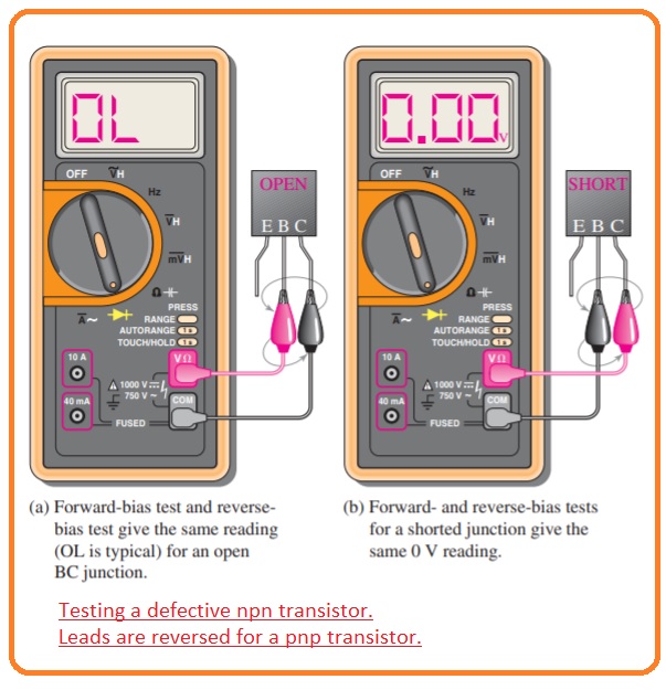
- In above figure circuit denoted as (a) red lead of meter is attached with the base of NPN transistor and black with the emitter to make forward bias base-emitter junction.
- If the junction is fine you will have values among 0.6 and 0.8 volts almost, with 0.7 volts for forward bias.
- In-circuit (b) leads are changed to reverse bias the base-emitter junction.
- If a transistor is operating well you will see the OL on the meter screen.
When the Transistor Is Defective
- If a transistor is faulted through an open point or inner connection, you will get an open circuit reading (OL) for both forward and reverse bias states to the junction as explained in below figure denoted as (a).
- if the junction of the transistor is short circuit there will be zero value on a meter for both forward and reverse biased test as denoted in figure as (b).
- Some digital multimeter has test socket on their front side to test a transistor for hFE value.
- If transistor is put not correctly in the socket or if it is not working accurately due to errored junction or interior linking a meter will show one or zero.
- If a value of βDC is in a normal range for a certain transistor than it working accurately.
- The normal range for βDC can be found through the datasheet.
Checking a Transistor with the OHMs Function
- Such a digital multimeter that does not have a diode test position of hFE socket used open or shorted junctions by setting the function switch to an OHMs range for transistor test.
- For the forward-bias checking of fine transistor PN junction, we will receive resistor value which can change according to inner battery of meter.
- of a good transistor
- Numerous digital multimeters do not have enough voltage on the Ohms range to completely forward bias a junction, and you can get value numerous 100 to numerous 1000 ohms.
- To reverse biasing checking of fine transistor we will receive out of range sign on mostly digital multimeters since the reverse resistor is larger to find.
- According to meter out of range signs can be showing one or displaying dashes.
- Though you can not get exact forward and reverse resistance interpretations on a
meter, the relative interpretations are adequate to specify a correctly operative transistor pn junction. - Out range indication displays that the value of reverse resistance is very large as you thought.
Transistor Testers
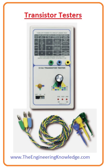
- The transistor tester can test the transistor both in-circuit or without circuit.
- Let’s suppose that amplifier circuit designed on the PCB board is get malfunctioned.
- A accurate troubleshooting shows that we do not unsolder any element of design on PCB until we are not assure that it is faulted.
- When any element is separated from the board it is a chance of damaging the contact and traces of the PCB board.
- We can do the in-circuit check of the transistor through using a transistor tester shown in the below figure.
- The 3 clip leads are attached with the terminals of transistor and tester shows positive results if transistor is fine.
So, friends, it is a detailed post about How to Troubleshoot Transistor (BJT) Circuits if you have any query ask in comments. Thanks for reading.

