 Hello readers welcome to new post. In this post, we learn FM Receiver PCB Based Arduino Project. FM receiver is the main part of radio that used to get the signal send from the transmitter and convert in the sound that we can hear through the use of a radio speaker. Its common circuit is very easy to understand and can be used to practical understanding. The receiver has a proper configuration to get the signal from the sender end and after getting the signal to convert it in the audible signal. In this post, we will learn the basic circuit of the FM receiver and will create it with the use of the Arduino module and will see how it works with that device.
Further, i want to mention that the PCB board that we are going to use in this project is designed and constructed through best PCB supplier that is PCBWAY. It is a china based PCB designer and manufacturers that are offering different PCB-based services to all over the world. Their quality and good cost services are making prominent to all over the world and new customers trusted them to get the services. These projects also created with their support and collaboration since i am a regular user of the services they offer different discounts and projects collaboration for their users. If you are new and have not funds for your projects they also offer coupons for their customers that can not afford the project’s cost. You must also avail this feature with that their community for projects is existed where you can share your projects and good projects also get the reward. In simple words, it is the best PCB supplier and customer that never compromise on quality and best services. You must also avail of their services. So friends come to our project and discuss it. Let’s get started.
Introduction to FM Receiver
- It is the module that used to make data transmitted received in radio communication.
- Generally, there is 2 main categories of data transmission is employed in radio communication first one is frequency modulation that is FM, and the second one amplitude modulation or AM.
- If we do comparison these two modulations then we will come to know that FM technique has the ability to send the signal with less sound-to-noise ratio, good quality, and less interference.
- There are 3 main parts of radio signal transmission first one sensing of signal, the second one is a receiver and the third one is the conversion module.
- The operation of the receiver is to convert the signal received in audible form.
- The main parts of FM receiver are three first one is the antenna second one filters, and the third one is an amplifier.
- The antenna is used for the detection of the frequency of the signal.
- Filters are types of electronic and used to separate the required signal from other non-needed signals.
- While an amplifier circuit used to amplify the strength of the signal.
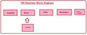
- The basic operation of the receiver is explained here through its basic circuit.
- Its radio frequency amplifier get the signal through the antenna and eliminate the nor required signal part and amplify it.
- THen signal moves to the mixer part that consists of frequency variation circuitry and varies the frequency to the desired level.
- The resultant signal goes to filter circuitry and makes the signal properly configured.
- After that signal goes to the demodulator and a modulation process occurs on it.
- In the final step, a signal is converted in audible form and can be heard from the speaker.
FM Receiver PCB Based Arduino Project
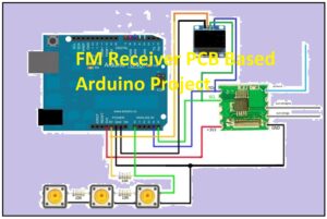
- The main parts of the project are listed here.
- PCB created through PCBWAY
- Arduino
- Buttons
- Resistances
- Capacitor
- LCD
- These projects will help to operate the radio channel to hear any program of your own choice from the frequency range of seventy megahertz to one hundred megahertz.
- The board over which all parts of the board are positioned is manufactured from the PCBWAY. WE send them the Gerber file with the required specification and they make our project with all required dimensions.
- This project works very easily and comprises of buttons link to LCD.
- Through use of these buttons, you can set the desired frequency channel of the radio. and which channels you select its frequency number will be shown at the LCD.
- Other buttons will be used to change the frequency level.
It is a simple project and can be designed very easily and operates in a semester project. If you are a new student and have less knowledge you must visit the PCBWAY to make this project. Their engineers will help you to make this from start to end with great details. That all about the post. If you have any query ask in the comments.


