SONY DSC
Hello readers welcome to the new post. In this post, we will have a detailed look at Battery Charger Circuit Simulation. In this project, we will make a charger that can be used to charge different electronic devices at different voltage levels. For getting the different values of voltage in this project I am going to use LM317 that is a voltage regulator that regulates the voltage at different voltage levels. These projects can help you during semester projects to work on different levels and simulations.
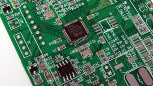
Here I want to mention that the PCB boards that we are going to use in this project are the most reliable and best in all services that is JLCPCB. Their main services are in different types of PCB boards like single layer, double layer, multiple layers, with and they offer services related to project simulation and manufacturing at affordable prices. It was established in 2006 and offers different services related to PCB and its related parameters all over the world at affordable prices.
Ensuring quality and its consistent improvement are the two main guidelines of the company.
Their advanced PCB technology permits them to offer high-precision boards suitable for industrial, military, aerospace, and medical applications. JLCPCB has been at the forefront of the PCB industry. With over 14 years of continuous innovation and improvement based on customers’ needs, they have been growing fast, and becoming a leading global PCB manufacturer
Here I want to mention that the parameters that we send them to make in this board were accurately placed in our projects and with great accuracy and affordability. So let get started.

Introduction to LM317
- Our main component in this project is LM317 first of all discuss it.
- LM317 is the variable voltage regulator that offers different values of voltage in the range of 1.25 to 37 volts and current values of 1.5 amperes.
- Its input voltage range is three volts to forty volts.
- It is a very common voltage regulator and employed in different projects to regulate the voltage.
- At this device, there is in built current limiting module and protection from the high temperature.
- Its main advantage is that it makes the circuit of any project simple since it is the replacement of a large number of voltage regulators since it provides different values of voltage.
- It used in the creation of a power supply with different voltage levels.
- There is three main pinouts of this device and not has ground pinout that generally lies in different regulators.
- It has features to regulate the larger values of voltage like forty volts.
- Its power dissipation can be measured through the use of this formula.
Power Dissipation = (Vin – Vout) x Iout
Specifications of LM317
- The main features of LM317 are mentioned here.
- Its voltage regulation range is three to forty volts at inputs.
- It’s available in TO-220 packaging.
- its volts range is 1.25 to thirty volts at outputs.
- The current value is 1.5 ampere.
Battery Charger Circuit Simulation
- The main parts of our project are mentioned here.
- LM317 used as a voltage regulator
- Didoes used for rectification
- Capacitors
- Resistances
- Switches
- Fuse
- Transformer for voltage value change
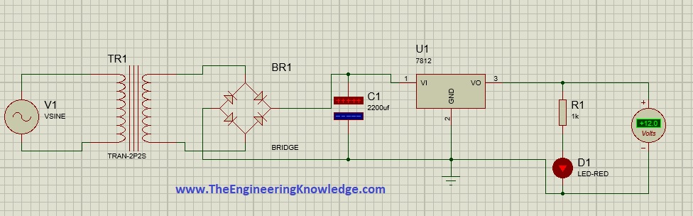
- In the above figure, you can see the circuit of this project that consists of the above-mentioned components.
- The first element is a transformer that changes the voltage level and after that, with the output of the transformer, their bridge circuitry is linked that is used for voltage regulation.
- Voltage regulation is a process through which AC volts are converted into dc as our requirement is DC we are using the bridge.
- In this project, we are using 7812 which offers 12 volts you can see our output volts are constant, and forgetting the variable voltage level use LM317.
- The output of the bridge is not pure dc but it has some value of ripples that consist of pulsating DC to remove those pulses there is use of capacitor that removes the pulses and makes our DC pure and sends to LM317 or 7812 converts that volt to according to our requirements.
- These voltages go to loads and are used by it here our load is LED and you can see it is blinking.
So friends that is all about the Battery Charger Circuit Simulation. If you still have any query ask in the comments thanks for reading. Have a nice day thanks for reading. Here I further want to mention that this project is designed with the collaboration of JLCPCB. That offered the good quality PCB you must also avail the services of this supplier.