 Hello, friends welcome to onboard. In this post, we will have a detailed look at H Bridge DC Motor Driver. The movement regulation of DC motor is the variation of specific dc motor drive fact which control the movement of the direction of the motor. There is numerous applications in industries and projects where the direction of movement of the motor is needed for certain applications. An example of control of the direction of the motor is conveyor belt generally which used for different types of the inspection process in the different category of industries and factories.
This category of conveyor system needed two-direction motor regulation to do the inspection procedure with a high value of precision. Here we will cover the process of H bridge configuration with the detailed that help to control the direction of the motor. So let’s get started.
Introduction to H Bridge Motor Driver
- The H bridge motor drive circuitry used to provides the voltage about the output or load in different directions. It is created with the use of 4 switching components that are transistors or MOSFET. The basic application of H bridge circuit is run the motor in any direction installed in robots and some other related applications.
- This circuit also employed in DC to DC, AC to AC, and DC to AC converter circuits.
- PCBWayis china based PCB provider and manufacturer. Shenzhen is the Research and development center for the world for the last few years where this manufacturer is located.
- With having features and experience of larger than the previous ten years in the process of PCB manufacturers and related services PCBWAY always try to fulfill each and every requirement if their users.
- The more important features that distinguish it from other manufacturers is their fast and given time delivery of the product, high quality, reasonable price and special types of offers for their customers.
- It is now a highly experienced supplier located in china. They have proud to be the best business collaborator with that good fellow in each and every factor of your PCB-related requirements.
H Bridge Circuit description
- This circuit configuration is generally created in the form of ICs.
- This circuitry is nominated as H bridge since there is H like arrangement is used in the project.
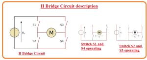
- Its structure is very basic that comprises of 4 switches configured as S1 S2 S3 and S4 can see in the below figure.
- For the circuit creation of this project, we get the designing services from the most reliable and trustable PCB supplier PCBWAY.
- the circuit configuration is such that if switch S1 and S4 are closed other two in the open state then the positive cycle of voltage is given to the motor.
- Now if we change the switch’s position from S2 and S3 in the close state then the motor operates in the reverse state and operates in opposite direction.
- Here should take some precautions during this operation that there should not switch an S1 and S2 close at the same time interval other wise short circuits will occur. These precaution measurements are also applicable to the other switches.
H Bridge Circuit Components
- The main components used in this circuit configuration are described here with detail.
- Relay
- H bridge generally created through the use of relays connected in form of the sequence-like array configuration.
- In some projects there is DPDT relay is employed but mostly prefer is semiconductor-based H bridge due to less prices large operating speed qualities.
- Using N and P Channels
- The solid-state H bridge configuration is created through the change in polarity like PCB configuration of BJT.
- With that, there is such arrangements in which there is P channel MOSFET is configured to the supply offering large value of voltage and N Mosfet to the less voltage supply that run the load according to the desired configuration
- With the Use of N channel
- This design configuration is most preferred for the H bridge since N channel MOSFET exists at high and less voltage part.
- The circuit configuration of this module is somewhat is complicated than others
H Bridge Motor Driver Applications
- The main applications of these modules are mentioned here.
- It used in different types of drones to regulate the speed and applications such as surveillance and terrain navigation.
- It used in AC to DC covnertros motor drivers.
- It used in robot servos and conveyor operations.
That is all about How to Create H Bridge Motor Driver Circuit if you have any further query ask in the comments. Thanks for reading have a nice day.


