 Hi readers I hope you all doing great. In today’s post, we will have a detailed look at different types of operational amplifiers circuit. In this post, we will discuss different types of operational amplifier circuitry which are commonly used in different electronic engineering applications. The common category of these circuits is a constant current source, current to voltage converter, etc.
In this post, we will discuss circuits, operation, and some related parameters of these types of operational amplifiers. So let’s get started with Explain and Analyze Types of OP-Amp Circuits.
What is Constant-Current Source
- The constant current source is a device that provides current to the output or load with constant value instead of variation in the resistance of the load.
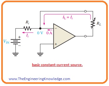
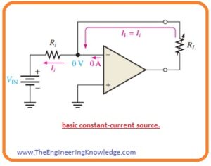
- In the below figure you can see the circuit configuration of constant current source where stable voltage source (VIN) is delivering a constant current by the input resistance.
- as the inverting terminal of the operational amplifier is at zero volts or ground the value of current Ii can be found with the use of Vin and resistance Ri.
Ii = VIN/Ri
- As the inner input impedance of the operational amplifier is very high in practical total current Ii is passing from load resistance RL that is linked with the feedback path. As Ii=IL
IL=VIN/Ri
- If the value of RL varies current IL remains constant till Vin and Ri have a constant value.
Current-to-Voltage Converter
- The current to voltage converter transforms a changeable current at an input in the output voltage with a direct relation with the current.
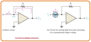
- In the below figure you can see the basic circuit configuration.
- As in the practical net of current Ii is passing through feedback path the voltage loss abut the resistance Rf is IiRf.
- As you can see the left side of resistance Rf is linked with zero volts the value of voltage is equal to the resistance Rf volts that are in direct relation with Ii.
Vout=IiRf
- The certain application of this circuitry is explained in figure denoted as b, in this circuit photoconductive cell is connected for sensing the variation in the light strength.
- With the change of light intensity, the current movements through the photoconductive cell also change since cell varies in resistance.
- This variation in the resistance value generates a direct variation in the value of output voltage.ΔVout =ΔIiRf).
Voltage-to-Current Converter circuit
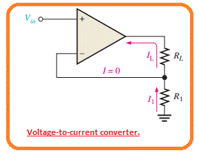
- The basic circuit configuration of voltage to current converter you can see in below figure.
- This circuitry is applicable in such an application where it is compulsory to have load current which is regulated with the input voltage.
- If we get ignore input offset voltage then input terminals of operational amplifier which are inerting and non-inverting have similar potential.
- so the voltage about Ri is equal to Vin. As there is ignorable current at inverting terminal the current passing through the resistance Ri is like to the current passing the load resistance RL.
IL=Vin/R1
What is the Peak Detector
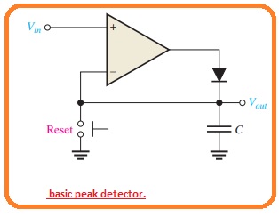
- There is very interesting application of the operational amplifier is a peak detector circuitry configuration as you can see the below figure.
- In this circuit configuration, the operational amplifier is used as a comparator. The circuitry configuration is used for the detection of the peak value of the input voltage and store the peak voltage on a capacitor. For instance,
- This circuit configuration can be used for detection and storing the extreme value of voltage surge this value can be calculated at the output terminal with the use of a voltmeter.
- Its working principle is to explain as. If we apply the positive value of voltage the non-inverting input of the operational amplifier large value of output voltage of the operational amplifier causes the diode to go in forward biased state and capacitor get charged.
- The charging process of the capacitor continues until the point the voltage of the capacitor equal to the input voltage and it causes the inverting and non-inverting terminal of operation to become at the same level.
- In this case the operational amplifier comparator switches and output become less level. The diode has now reversed a biased state and the capacitor stops to get charged.
- Its voltage value is equal to the peak value of Vin and will retain this voltage till the charges start to leak out.
- If the larger input peak exits the capacitor gets charged to the new peak value.
So that is all about types of operational amplifier circuits I have explained these circuits with the detail. If you have any further query ask in comments. thanks for reading. have a good day.

