 Hello, readers welcome to the new post. Here we will discuss Solar Battery Charger Circuit. Solar technology currently has become very common and almost all big industry homes and buildings are transforming to solar energy. With that solar operating devices are prevalent in common uses and at an advanced level. Solar operating devices are also in use at space stations where there is no electricity.
In today’s post, we will make a circuit of a battery charger that is operated on solar energy and has the ability to provide 12 volts to load. In this project, we will use 7812 and 7805 voltage regulators that will provide us 12 volts and 5 volts respectively. Through chargers, we can operate the devices up to five and twelve volts.
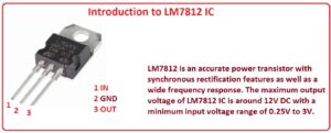
Introduction to 7812
- The 7812 is a voltage regulator that can provide twelve volts at the output with one amper current and its input volts value can be from 14 to 35 volts
- It operates as a linear regulator and operates at dc input. For its operation, there is no need for an exterior certain configuration.
- The LM7812 component works as 2nd generation module since it helps to enhance the working operation of one phase power supply.
- It is considered as the finest option for battery management operations. There are different types of pin combinations assembled on the circuit to make connections with any type of device for operation and also can link to circuit boards. In this project, we will configure to PCB get from JLCPCB
| Features | Value |
| Input Voltage | 14.5V to 27V DC |
| Output Voltage | 11.75V – 12.25V DC |
| Output Current | 1A |
| Peak Current Capacity | 2.2A |
| Dropout Voltage | 2V |
| Package Type | TO-220 |
LM7812 Pinout
- There are three main pinouts it has are listed here.
- IN: Here input of positive polarity is provided.
- Out: From this pinout, the output is taken.
- GND: Here ground is linked.
Introduction of 7805
- The 2nd main component of this circuit is 7805 which is also a voltage regulator used in electronic circuits and its output volts are plus five volts with variable volts at inputs
- its output volts are constant. The number 78 in this component is positive voltage regular and 05 denotes its output volts. So it provides the positive five volts
- Its input volts range is seven to twenty-five volts
- The operating current for this module is about five milliamperes
- It comes with features of inner thermal overload and short circuit current limiting protection
- its junction temperature value is about one twenty-five C
- It comes in TO-220 packaging
- Till now we have discussed the main components of our projects that will help us to understand the circuit
Solar Battery Charger Circuit
First, we will discuss the specification of our circuit
Solar Charger Circuit Features
- We using a solar panel of 5watt
- Output volts are 5V and 12 V
- Voltage regulation +/- 100mV
- The highest output current is about 0.29 amperes
- Input volts 7 to 30 volts
Working Principle of Solar Charger circuit
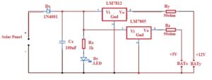
- The working principle of this circuit is that the charge control circuit will generate the constant value of volt. The current from diode Dx goest to LM7812 converts to 12 volts and the current also goes to 7805 converts to 5 volts and respective five and twelve volts battery gets charged
Solar Charger circuit and Components
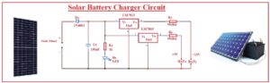
- Below figure you can the diagram of our circuit with the components listed here
- Solar Panel
- Diode
- Capacitor Resistances
- Battery
- 7812 and 7805 Voltage regulators
- LED
Circuit Explanation
- In this circuit, we used five-watt power that gives twelve volts through getting the light from the sun and transforming it into electricity. In this circuit, you can see that the diode denoted as DX having type 1N4001 is used to stop the reverse current flow towards the solar panel.
- There is an LED is linked to the circuit with resistance Rx that denotes the movement of current.
- There are 2 voltage regulators 7812 and 7805 connected to the circuit for voltage conversion into required volts.
- The voltage regulator 7805 output is five volts and 7812 gives twelve volts.
- The two resistances on the output side is Ry and Rz which retain the current save level. Through the use of the output of this circuit Nimh and LI, Ion batteries can be charged.
- This circuit has features to get the different values of output volts for this just link the voltage regulator
Solar Battery Charger Operation
- For operation make the connection of all components according to the circuit
- The solar panel must be in sunlight then set volts through regulators and check the output at a millimeter
Advantages
- The advantages of this circuit are listed here
- It has very little battery discharge when no sunlight exists
- Its circuit is simple and less expensive components are used
- can get variable output volts
Read also
- Solar Wire Size Calculator
- Solar Battery Charger Circuit
- Introduction to CN3065 Mini Solar Charger
- Solar Battery Charger Project with LM317
That is all about the Solar Battery Charger Circuit all details have explained. If you have any queries, ask in the comments. Thanks for reading