Hello, readers, welcome to a new post. Today we will learn HOW VARIABLE RESISTORS WORK. Resistors play a central role in the electric circuitry. Different types of resistance exist and are employed in different applications. Commonly used types of resistors are fixed variables based on their resistive value.
In this post, we will cover the basics of variable resistors’ working features and some other points. So let’s start with HOW VARIABLE RESISTORS WORK.
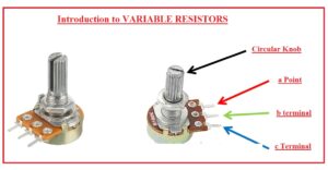
Introduction to VARIABLE RESISTORS
- The variable resistor is a category of resistance that varies resistance from 0 to a specific value. Its common applications are for voltage regulation.
- Its function is that as the value of resistance is increased for this module, current flow decreases.
- It is an electromechanical transducer and works through a slider contact at the resistive component.
- If it is used as a potential divider through the implementation of 3 points named potentiometer.
- In the case of two points, it works as a variable resistance and is called a rheostat.
- There are electronically implemented resistors called digital potentiometers.
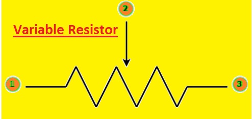
Definition of Variable Resistor
- The variable resistor is known as a potentiometer or is also called a rheostat that is part of circuits to change resistance. It is a passive device that has 3 pins that help to change the resistance of the circuit in the position of the moving wiper that is on the resistor.
- These modules are part of the circuit for controlling the current and voltage of the circuit and are also used for gain amplification.
- It comes in different sizes and designs based on applications.
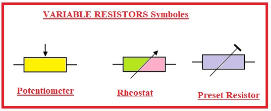
VARIABLE RESISTORS Symboles
- Here you can see symobls of variable resistors
What is a variable resistance?
- Variable resistance of electrical component that is used for setting resistance. These features make variable resistors effective tools for different applications.
- It is part of circuits for current control flow.
- • A variable resistor is used for audio circuits. A potentiometer is a variable resistor that is part of the speaker.
- The main uses of variable resistors for audio circuits. Potentiometers work as variable resistors for speaker volume control and headphones.
- By setting potentiometer resistance, we can set the volume of the audio signal. It is also used for dimmer switches and setting the resistance brightness of light.
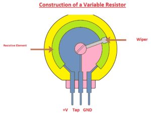
Construction of a Variable Resistor
- This resistor has a resistive component and a movable wiper that moves on the resistive element. The resistive element can be in the shape of a thin layer deposited on a ceramic or plastic substrate. The resistive elements can be varied by changing the length or thickness of the resistive material or by varying the pitch of the wire, also the wire diameter.
- The fixed terminals are mostly created with metallic substances like copper or brass and attached at endpoints of resistive elements.
- • The wiper has a connection with one fixed terminal, and the resistance value between the wiper and other fixed points changes with the movement of the wiper.
- Variable resistors can be designed in different shapes and sizes on the basis of users. These resistors are designed to be used in PCB boards and also for panel mounting. They come with different resistance values, power ratings, and other features according to use.
Operation Principles of Variable Resistors
- The working principle of variable resistors is based on the change in resistance by adjusting the position of the moveable wiper across resistive components. The resistive component is created with the use of carbon, wire wound, or conductive plastic.
- During the movement of the wiper, the resistive component creates a new electrical path among the two fined points of the resistor, which varies the resistance value among these two points. If the resistance value is increased, current in the circuit will decrease, and if the resistance is reduced, current in the circuit will be increased.
- The relation between the wiper position and the resistance value is linear or logarithmic on the basis of the variable resistor type. For linear resistors, the resistance value varies in proportional relation to the wiper position, and in the case of the logarithmic variable resistor, the resistance value varies in a logarithmic way.
Adjustable resistor vs. variable resistors
Adjustable Resistor
- An electrical component that enables user-adjustable circuit resistance
- Its main types are trimmers with single, multiple, linear, and logarithmic turns.
- Its resistance range is some ohms to kiloohms.
- The knob or lever moved for changing resistance value.
- Common uses are voltage regulators, gain controls, oscillator circuits, bias adjustments, timer circuits, tone controls, and voltage control.
Variable Resistor
- a device for electronics that enables circuit resistance to be changed.
- Its main types are trimmer, linear, and logarithmic, with single or several turns.
- Its resistance ranges are several megaohms.
- Through rotating the knob or moving the lever, the resistance value varied.
- Its uses are for gain control, timer circuits, oscillator circuits, and voltage regulators.
Types of Variable Resistances
Single-Turn
- It changed with turning a slider or knob, and its range is some ohms to kiloohms. It is used for timer circuits, oscillator circuits, and oscillator gain.
Multi-Turn
- It has high resistance values and is like a single-turn variable resistor. It varied with turning the knob many times. Its main uses are for calibration of tests and measuring instruments and radio frequency tuning.
Linear
- In this component, with respect to wiper point resistance, change in a linear way. It’s used for tone control and volume control.
Logarithmic
- The resistance changes in a logarithmic way as a result of wiper movement. It is used for gain control, voltage regulation, and audio control. It is a main component for audio circuits since it has consistent attenuation of sound.
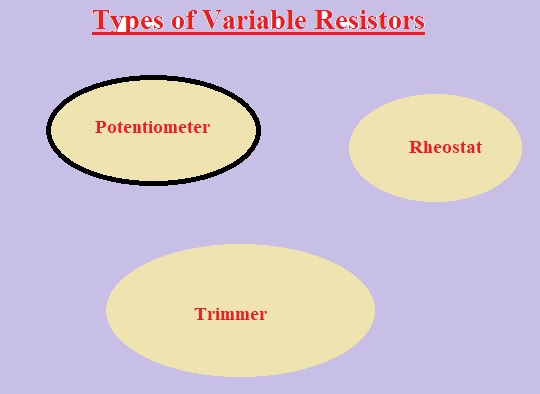
Types of Variable Resistors
- There are three main types of variable resistors are discussed here
- Potentiometers
- Rheostats
- Digital potentiometers
What is a potentiometer?
- For the potentiometer to change the resistance in circuitry, a rotary knob is used. There are three pinouts configured on the potentiometer.
- Among the 2 pins configured on the outer side, their resistive element exists and is used for resistance changes.
- A central pinout is used as a wiper. This wiper is configured among the 2 endpoints.
- Points can be moved to the connection resistive elements by operating the shaft of the potentiometer.
- If we move the wiper or slider to the left side, decrement in the resistance among the central pins and left-positioned pin. So resistance between the central pin and right pinout increases when the slider moves to the left.
POTENTIOMETERS as VOLTAGE DIVIDERS
- The voltage divider is circuitry used for the reduction of volts in a circuit. The output volts rely on the ratio of 2 resistances linked in a series combination.
- Output is gotten among the 2 resistances. The formula for voltage dividers to measure the volts is given.
- • Vout = R2/(R1+R2) x Vin
- Ri is the resistance nearest to input volts, and R2 is the resistance near to the ground. Vin is the input, and Vout is the output volts.
Potentiometer vs. variable resistor
Potentiometer
- A potentiometer is used as a voltage divider or to adjust the resistance of circuitry.
- Its design has a resistive component and a sliding contact that moves over the element.
- Its types are linear potentiometer and logarithmic potentiometer.
- Generally a few ohms to several megaohms has resistance value.
- Its tolerance is ±5% or ±10%.
- It has a high or low temperature coefficient based on type.
- It has features to handle high power of many watts.
- It has a sensitive nature for vibration and wear.
- Its main uses are for tone control, volume control, variable gain circuits, and voltage regulators.
- Its main limitations are its sensitive nature to wear and vibration and its high cost as compared to variable resistors.
Variable resistors
- Variable resistors are used to adjust the resistance of a circuit.
- Its main types are single-turn variable resistor and multi-turn variable resistor.
- Its resistance value is some ohms to several kiloohms.
- Tolerance value is ±5% or ±10%.
- Temperature coefficient is low or high based on type.
- It has a low power rating of about one watt.
- It is more durable than potentiometers.
- It is less costly than potentiometers.
- The main uses are gain control and timer circuits. Bias adjustment, oscillator circuits
- It has a limited range of resistance, less accurate than potentiometers.
DIGITAL POTENTIOMETERS
- This potentiometer used digital signals to vary the resistance in place of mechanical movement for resistance change.
- Digital potentiometers vary resistance stepwise on the basis of the digital signal moving through them. It is used for applications with vibration, dust, and moisture.
Rheostat
- The physical structure of rheostats is like that of potentiometer, and the difference is that rheostats are not used as potential dividers but work as variable resistance.
- It works on the 2 terminals in place of three point-like potentiometers.
- Its one point is connected at the resistive component and the second at the wiper of variable resistance.
- It has been used for power regulation circuits in series combinations like a light bulb.
- Currently not used for power control circuits since power losses occur
- In power regulation applications, the rheostat is replaced with switching circuits.
That is all about how variable resistors work. All details have been explained. If you have any further queries, ask in the comments.


very detailed explained