 Hello, readers welcome to the new post. In this post, we will learn Introduction to IRLZ34N N-Channel Power MOSFET.MOSFET stands for metal oxide semiconductor field-effect transistor type field-effect transistor such as JFET. As we know that in JFET pn junction comes out but in MOSFET it does not come out. Instead of its MOSFET gate, it is separated from the channel by a layer of silicon dioxide. There are 2 main types of MOSFET first enhancement and second diminution described as D.
This MOSFET component is used in such an application where high speed and power are required as it provides these features and, with a small amount of resistance. It is the N family of the MOSFET channel. Since this is the N channel so the flow of the current or running process is done by free electrons. Here is a very important fact that I am to discuss is that to create different projects related to electronics if you are a student or beginner can contact different electronic engineering-related companies that will help to you create such products and also provide some components at a reasonable price to you for creation of a project. There are numerous companies are working in this world that provide services related to electronics but I will suggest to PCBWAY. The services of this company I also have used I also recommend it you. Its most common services are PCB, PCBA, and PCB prototyping. They provide $30 for SMT orders and three flexible options are Turnkey, kitted, and combo. You can choose these options while getting components from them.
PCBWay is dedicated to meeting the requirements of its clients from a variation of industries in terms of excellence, delivery, cost-effectiveness, and other demand requests. As one of the most skilled PCB producers in China. PCBWAY take pride in being your best business associates and best network in all features of your PCB requirements

So let get started.
Introduction to IRLZ34N N-Channel Power MOSFET
- High-strength N MOSFETs (Metal – Oxide – Semiconductor Field-Effect Transistors) are famous for driving high levels of volts and currents from a microcontroller.
- They have very low ON resistance thirty-five milliohms) which is why they consume less heat and usually do not need a heat sink
- The IR MOSFET power family MOSFET power is used by various devices to support various applications such as DC motors, inverters, SMPS, lamps, charging switches, and battery-powered applications.
- This electronic component is widely used in electric circuits and from 1960 to 2018 approximately (1.3 × 10²²) MOSFETs have been created.
- It is also widely used in digital circuits, analogs and power tools.
- The main advantage of MOSFET is that there is no need to install current to control the current load is required for BJT.
- The power supply provided to the E-MOSFET gate can increase the conduction of the condition.
- While the D-MOSFET voltage supplied to the gate can reduce the conduction of the condition.
- The transition speed of this phase is high, their size is small, using less power.
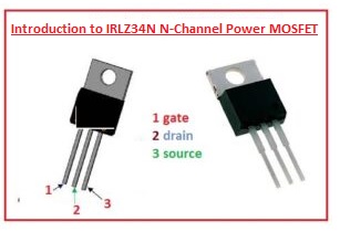
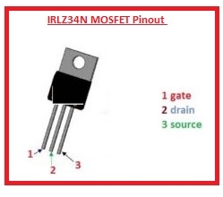
IRLZ34N MOSFET Pinout
- There are three main pinouts that are listed here
- Source: This pinout is used to get out the current from the device
- Drain: current goes from outer source to module
- Gate: It works as a control terminal like the base in BJT
IRLZ34N MOSFET Working
- It operating mode is the enhancement mode of MOSFET and it is employed as a switching module in different projects.
- Outer supply is provided at the gate terminal and it operates as switch current flows from drain to source
- It is considered a mechanical switch since there is no existence of a moving component
- There is such an arrangement that gate has insulation from the drain and source and these terminals work as plates of a capacitor and there is a positive charge at the gate and a negative at the source and in this way, it operates
- If there is volts value of the GS is 0 it gets off and removed from the switching mode
IRLZ34N MOSFET Features
- Its main features are listed here
- Its height and length is 15.65 and 10 millimeters
- Its width is 4.4 millimeter
- It used rise time about one hundred nanoseconds
- Fall time for this device is twenty-nine nanosecond
- It is available in T0-220 packaging
- Its dissipate power value is sixty eight watt
- value of volts about VDS is fifty volts
- Volts about VGS is plus sixteen also minus sixteen
| Features | Details |
| MOSFET Type | N-Channel |
| Voltage Rating | 55 V |
| Continuous Drain Current | 47 A |
| Pulsed Drain Current | 188 A |
| On-Resistance (Rds(on)) | 0.022 ohms |
| Gate Threshold Voltage (Vgs(th)) | 2.0 V to 4.0 V |
| Gate-Source Voltage (Vgs) | ±20 V |
| Total Gate Charge (Qg) | 38 nC |
| Gate-Source Threshold Voltage (Vth) | 1.0 V |
| Input Capacitance (Ciss) | 2000 pF |
| Output Capacitance (Coss) | 450 pF |
| Reverse Transfer Capacitance (Crss) | 250 pF |
| Switching Speed (tf/tr) | 44 ns / 20 ns |
| Operating Temperature Range | -55°C to 175°C |
| Package | TO-220AB |
Applications of IRLZ34N
- Its main applications are listed here
- It is the main part of a circuit that used to convert DC to DC and DC to AC
- It used in EPS devices
- It works as the driver of the relay
- It employed in battery
- Motor drivers are consists of this device
- It used in regulators are the main component
- Also employed in different types of UPS
IRLZ34N N MOSFET Equivalents
- RFZ34, IRFZ34A, IRFZ34NS, IRFSZ24A, MTAJ25N06EL, MTP25N06V, MTP30N06EL, MTP30N06VL, IRFZ34NL, IRLZ34NS, IRFZ34S, IRLZ34,
- IRLZ34N, IRLZ34NL,IRFZ34E, IRFZ34N,IRFIZ24E,
- IRFIZ24G, IRFIZ24E, IRFP153(R), NDP5060, PHX15N06E
How TO test the ON and OFF states of the IRLZ34N MOSFET
- For testing the MOSFET, use DMM and set the value to diode parameters. For testing the MOSFET in the OFF state, leave the gate without using voltage on it and check the connection between the drain and source.
- Then connect the negative probe of the DMM with the source and the positive pin with the drain.
- DMM shows OL, gives a small voltage to the gate pin, and notes that it is working as a small capacitor.
- For this, use the positive probe of DMM and connect for some time gate pin and make a connection of the positive probe with the drain.
- There is now a short circuit so the gate is charged up and the MOSFET is in an on state. For making the MOSFET again in the off state, discharge the gate. It is a small voltage that connects the gate and source with a finger for discharge, and as a result, the MOSFET will get turned off.
Absolute Maximum Ratings:
- Do not use MOSFET at absolute maximum ratings and set reading less than 20 percent.
- Maximum continuous drain current is 30 amps, so do not connect a load of more than 24 amps.
- Use an accurate heatsink, and the maximum drain-to-source voltage is 55 volts, so do not use a load more than 44V.
- Storage and working temperature range for MOSFET is -55 °C to +175 °C.
IRF3708 vs IRLZ44N
| Features | IRF3708 | IRLZ44N |
| Voltage Rating (Vds) | 30V | 55V |
| On-Resistance (Rds(on)) | Lower values | Slightly higher |
| Package Type | TO-220 or D2Pak | TO-220 or TO-262 |
| Gate Threshold Voltage | 2.0V to 4.0V | 1.0V to 2.0V |
| Gate-Source Voltage | ±20V | ±20V |
| Total Gate Charge | 28 nC | 38 nC |
| Switching Speed | Faster switching speed | Slower switching speed |
Read also