 Hello, friends welcome to the new post. In this post, we will have a detailed look at Balanced Three-Phase Circuits Voltage and Current Calculation. the system having the same magnitude of three phases but with a difference of one twenty-degree of phase, the angle is called a balanced three-phase system. Here we are going to discuss the details about the voltage and current flowing in this system.
Generally, a three-phase system is used for the transmission of volts from one point to other from generation to load end. So let get started
Balanced Three-Phase Circuits Voltage and Current Calculation
- In a power system, the power is generated through the use of three-phase generators.
- The load linked to the three phases of generators is balanced it means the impedance values are the same.
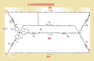
- in the below figure the generator configured with wye connection having natural wire n.
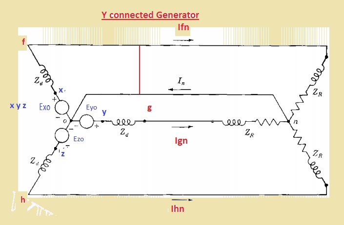
- To understanding of this circuitry let us assume that the value of impedance and load is zero and also between points 0 and n also zero
- the resultant circuitry of this generator has emf in very phase and denoted with a circle.
- Each emf is configured in a series combination to the resistance and inductive reactance linked to Zd.
- The points x y and z are reference points
- and terminals of generated with f g h
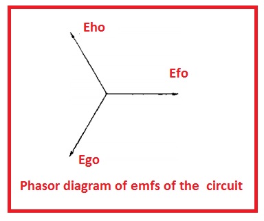
- In this circuitry, the value of emf denoted with Exo, Eyo, and Ezo has equal magnitude and separated with one twenty degree of angle
- Let suppose that value of every emf is one hundred volts then Eao was taken as a reference then we have
- Exo = 100∠0V
- Eyo = 100∠240V
- Ezo = 100∠120V
- Here phase equation is fgh.
- In other words Exo leads Eyo by one twenty-degree and Eyo leads by Ezo one twenty degrees.
- In below figure, we can see the phase sequence
- The voltage about the terminal is given here.
- Vfo=Exo-IfnZd
- Vgo=Eyo-IgnZd
- Vho=Ezo-IhnZd
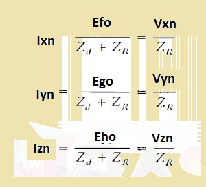
- as o and n has the same value of potential so Vfo Vgo Vho has the same value of Vxn, Vyn, Vzn
- Equation of line current are mention here
- Exo, Eyo Ezo has the same value of and one twenty-degree phase difference.
- Vfo, Vgo Vho also has hs same values and one twenty degrees phase difference
- In below figure you can see the 3 currents flowing in the system having balance configuration. In figure denoted as b their closed triangle is shown.
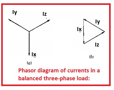
- So the curent flowing in the neutral is zero.
- in case of nonbalance load, the current summation is zero and the current is passing among the points n and o.
- in the non-balance system, there is not the same potential till they are linked to 0 value of impedance.
- Due to phase variation in the voltage and current in case of a balanced three-phase system, it is easy to simple to use such a technique that denoting th phasor through one twenty degrees.
- The outcome of the product of 2 complicated numbers is the multiple of their magnitude and angle sum
- If the complicated number denoting phasor is multiplied to a complex number of unity magnitude and angle θ the resultant complex number denotes phasor equal to real phasor parted with the angle of θ.
- The complex number if unity value and angle is a function which that moves the phasor at which it works with angle
- In math the operator, j caused the rotation of ninety degrees and operator -1 that results in one eight degrees.
- 2 continues usage of operator J results in 90+90 that results in j x j cause to rotation at an angle off one-eighty degree.
- The a alphabet is generally used to represent the function that results in the movement of one twenty degrees anti-clock wises.
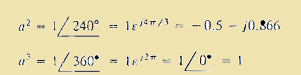
- This function is a complex number having a unity value having an angle of one twenty-degree and works as
![]()
- If we use function a two time then phasor will be moved with the angle of two forty degrees.
- With using three times angle move to three-sixty degrees
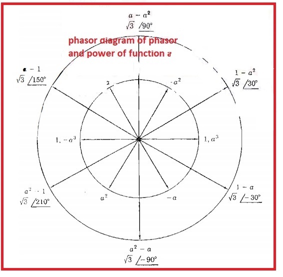
- In below diagram, we can see the phasor denotation having different values of a.
- The line to lin voltage for below circuitry are Vfg, Vgh and Vhf
- Following the path from f to g to the point n we have
- Vfg=Vfn+Vgn=Vfn-Vgn
- as the Exo and Vfn has not the same phase so we are replacing Vxn in place of Exo
- So in the below diagram shows the phasor diagram of voltage to neutral and vlaeu of Vfg is given here.
- In case of function we have
Vgn=a2Vgn
Vfg=Vfn-a2Vfn
- phasor equation
- In the case of phasor Vfg leading the Vfn through an angle of thirty degrees and has √3 has a large value.
- Other value of line to line can be found through using this method In the above figure we can all values of line to line volts
- the value of balance their phase line to line volts of three-phase circuitry same to √3 time the magnitude of line to neutral
So that is all about the Balanced Three-Phase Circuits Voltage and Current Calculation. If you have any further query ask in the comments box. See you in the next post