The electrical connectors are components that are used for the connection of one wire with another wire or cable. The electrical connectors are also used to connect different electrical components. On the basis of projects and circuit demands, different types of wire connectors are used that have their own features. Here we will cover the basics of wire connectors and other types. So let’s get started with an introduction to wire connectors.
What are wire nuts or wire connectors?
- In any electrical circuit or wiring, components are connected electrically for current flow between different devices. The electrical connectors, or wire nuts, are electromechanical components that make electrical connections between different parts of the circuit or also make connections between circuits by joining different parts of the circuits.
- The connection made can be removed if there are portable devices connected, and for permanent joints, make a strong connection.
- If there is a need for a connection of dissimilar connectors, an adapter is used. Some connectors have a plug that is called a male component and a socket that is called a female component.

How to Wire Connectors?
- If wires are connected securely and properly, current can flow. This is due to the wire connection of wires. Different wire connections have different working conditions, and some protect wires in closing protection. The main use of wire nuts is to make the connection between two or more wires.
- For using wire nuts, first of all, strip the wires and twist them before the wire nut is screwed.
Wire Connector Types
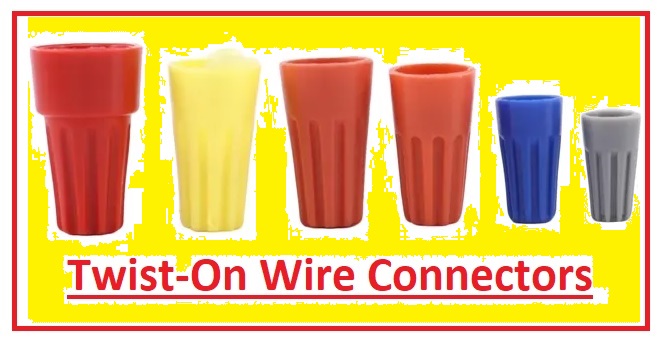
Twist-On Wire Connectors
- Twist-on wire connectors are called wire nuts or wire connectors that are used for the connection of wires. Twist-on-wire connectors are electrical connectors that connect two or more low-voltage conductors.
- It is mostly used in the USA and some European countries for residential wiring and industrial buildings for the wiring process.
- These connectors are also called wire nuts, cone connectors, or wire connectors. These connectors are also called Marrette in Canada.
- Twist-on wire connectors can be manually connected and come with external grooves for easy handling. They are color-coded to show connector size and capacity. Their main use is in place of terminal blocks or conductor soldering.
Winged Twist-On Wire Connectors
- A wiring twist-on-wire connector is best to use for commercial and also for residential. There is a wired, coiled spring in the plastic covering of this connector that has features for handling different wire combinations, saving conductors from corrosion and other environmental conditions.
- These connectors come with different wire ranges and are made with ribbed caps for easy connection. It has extra torque through the use of external wings on connectors. They come in yellow, gray, and blue colors.

Crimp-On Wire Connectors
- These are solderless electrical connections that employ pressure for connection. They are used for terminating standard wire, and the wire is put with an accurate size opening of the connector and crimper used for strongly squeezing the wire opening. It can be connected with a metallic plate through a separating screw or bolt.
- This type of connector is used for commercial and residential wiring systems. There is no need for certain tools for the connection of wires.

Push-In Wire Connectors
- Push-in wire connectors are insulated wire connectors that are equally used for residential and commercial wiring systems for lights and digital signage.
- It is used for conventional twist-on connectors. They can easily be used to make high-speed connections and come with color coding that helps to easily recognize.
- Their design helps to easily connect in a circuit, and there is no need for special tools for installation. They are normally self-latching; an inner spring clamp easily holds the wire.
- It has more than one port also but uses one conductor for one port.
Plug and socket connectors
- Plug and socket connectors are made with the use of a male plug and a female socket. Sockets are fixed with devices like chassis connectors, and plugs are connected with cables.
- Plugs come with one or more pins that are put in a mating socket. The connection between mating metal components is enough to make a connection and finish the circuit. The alternative of plug and socket connection works with hyperboloid contacts for making strong connections.
- For a multi-pin connector, it is best to use a pinout diagram for finding wire connections with pins.
- Some connectors are designed to connect pin and socket connections in a single unit and are called hermaphroditic connectors. Such types of connectors come with mating having male and female features.

Soldered connectors
- Plug and socket connectors are connected with wire or cable with the use of soldering conductors with the electrodes of the connectors. Soldered joints for connectors are simple and easy to use but have slow process. If wires are soldered to the back side of the connector, the backshell is used for protection of the connection. Metallic solder buckets come with a cylindrical cavity that the installer finished with solder before putting in the wire.
Wire Nut Sizes by Color
Gray wire nuts
- These nuts have features for handling 22 to 16 AWG and about 300 volts.
Blue wire nuts
- These connectors are used for ballast wire connections and have features to handle 22 to 16 AWG and about 300 volts.
Orange wire nuts
- It can handle a wire gauge of 22 to 14 AWG and a voltage value of 600 volts. It is used for fan fixtures and lights for making connections with switch wires.
Yellow wire nuts
- These connectors have features for handling wire 18 to 12 AWG and a voltage of 600 volts.
Red wire nuts
- It has features for handling 18 to 6 AWG and 600 volts.
How to Install Twist-on Wire Connectors
- First of all, turn off the power supply, and then strip wires about half an inch for two wires. Strip about 3/4 to one inch if there are two wires.
- Hold wire ends point and put wires in connectors and screw on clockwise until connectors completely twist.
- Pull on every wire to make sure wires are properly connected to connectors.
How many types of electrical connectors are there?
- Electrical connectors are defined in three types according to termination ends: board-to-board connectors, cable wire connectors, and cable/wire-to-board connectors.
What are the uses of electrical connectors?
- Connectors are components or devices used for the connection or disconnection of circuits. They can connect and disconnect with hands or through tools without the use of certain tools like soldering.
What are the parts of a connector?
- The basic components of connectors are contact springs, contact finish, and connector housing. The contact interfacing explains the physical connection of components of connectors that mated.
Which electrical connector is the most common?
- The commonly used type of connector is wired connectors. It is basic and mostly used. With the use of wired connections, signals are sent through wire-connected devices.
Why do we use electrical connectors?
- Electrical connectors are made for making temporary connections of conductive paths so current flows from one device to another device connected.
Why do we have different types of connectors?
- There are many types of connectors used in power systems, and each has its own features and applications. But all connectors have the same functions that connect and disconnect the circular course of electric current.
What are the features of electrical connectors?
- Connectors are differentiated based on pinout, connection mode, materials, contact resistance, insulation, ingress protection, and working life.
How are connectors classified?
- Connectors have three main types: cable/wire-to-cable/wire connectors, board-to-board connections, and cable/wire-to-board connectors. Normally, 6 layers of connectivity exist for electrical connections. Read our more Engineering Blogs
Read also
- How to Wire and Install an Electrical Outlet Receptacle?
- Introduction to Electrical Receptacle and Outlets
- Light Switch Wiring Diagram: A Detailed Tutorial
- What are Ballast wirings DIagrams
- What is Fluorescent Light Ballasts: How do they work?
- 4 Way Switch Wiring Diagrams
- Dimmer Switch Wiring Diagrams


