For consumer electronics, medical devices, and vehicle systems, it is becoming fast, small, and high-power since conventional PCB boards do not offer these features. High-density interconnect boards are the best option for engineers that need high functions into limited space and maintain good signal quality, thermal operation, and longer-term reliability. This tutorial covers details about what HDI PCBs are, different types and applications for different industries, main advantages compared to standard multilayer boards, and practical tips for choosing the right HDI PCB manufacturer.
What Is an HDI PCB?
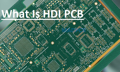
- A High-Density Interconnect (HDI) PCB is a PCB board used for higher wiring density per unit area than conventional multilayer boards. That density gets through using advanced manufacturing methods that help to provide good features and effective layer connections.
- Core techniques given through HDI boards are
Microvias:
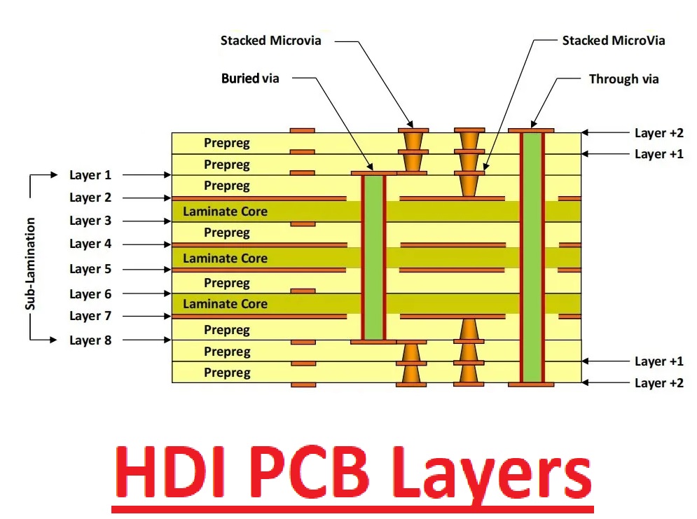
- laser-drilled holes smaller than 0.15 mm (often down to 0.05–0.10 mm). These small vias offer accurate interlayer connections with less space usage.
Fine lines and spacing:
- Trace widths and gaps are about 2–3 mils (50–75 µm) or finer in advanced designs.
Blind and buried vias
- Vias that make connections only to certain layers, compared to moving through the complete board, free up routing area over external layers
Sequential lamination:
- different lamination cycles that make complicated stackups layers with layers, helping layer counts without extra thickness.
These features help HDI boards be compatible with high pin count components like BGAs, QFNs, CSPs, and flip-chip ICs while minimizing overall board size and weight.
Common Types of HDI PCBs
HDI boards are defined by their structure and build-up complexity:
Type I (1+N+1):
- one building layer with microvias on each side of the conventional core. preferred for moderate-density usage and cost-effective projects.
Type II (2+N+2):’
- Two stacked microvia layers over each side. that provide good routing density and are used for mid- to high-complication designs
Type III (3+N+3 and higher):
- different sequential lamination steps through stacked or staggered microvias, best for high-density, larger layer count boards, part of servers, aerospace, and flagship consumer devices.
Any-Layer HDI:
- Microvias can be applied over all layers, giving high design options and routing efficiency. This is commonly used in smartphones, ultra-compact modules, and wearables.
Use the proper HDI type according to component density, signal speed needing thermal requirements, and cost
Applications of HDI PCBs
HDI technology shift from niches to mainstream is important for cutting-edge fields:
Consumer Electronics
- phones, tablets, smartwatches, laptops, and wireless earbuds based on HDI boards to integrate powerful processors, high-resolution cameras, multiple sensors, and long-life batteries into slim, lightweight designs.
- Flagship models of Samsung, Apple, and Huawei extensively use any-layer HDI for the best performance in minimal space.
Medical Devices
- Implantable devices such as pacemakers, portable ultrasound machines, wearable health monitors, and surgical robotics demand miniaturized HDI boards offering the required density and signal quality with the following required medical certification standards.
Automotive Electronics
- The advanced driver assistance system, autonomous driving modules, and electric vehicle battery management system use HDI for a high-speed, compact, and vibration-resistant design. For vehicles becoming smart, HDI follows continuously to grow rapidly.
Telecommunications and 5G/6G Infrastructure
- Base stations, switches, routers, and high-speed networking devices need HDI boards for handling GHz-level signals with less crosstalk and losses. Industrial IoT and robotics edge computing nodes, sensors, industrial controllers, and collaborative robot features from HDI have a mixture of small size, high component density, and reliable performance for harsh conditions.
- Some other fields are aerospace, defense systems, AI accelerators, and high-performance computing modules.
Benefits of HDI PCBs Over Standard Multilayer Boards
HDI PCBs provide clear technical and commercial advantages:
Miniaturization
- Smaller and lighter boards offer sleek product designs
Improved Signal Integrity
- A short interconnection path minimizes signal delay, crosstalk, and electromagnetic interference, which is important for high-speed digital and RF applications.
Better Thermal Performance
- Optimized layer stacking and via connections offer heat dissipation, important for power-hungry components.
Higher Component Density
- Fine-pitch BGAs and advanced packages are accurately positioned
Potential Layer Reduction
- Complicated design needed less number layers compared to standard multilayer boards that reduces thickness and sometimes cost.
Enhanced Reliability
- Microvias and sequential laminations that are accurately made offer quality interconnections with fewer failures in demanding applications.
HDI boards carry a high unit cost compared to standard boards, which reduces net cost with small enclosing, less material usage, and quality performance
HDI vs. Standard Multilayer PCB: Quick Comparison
| Feature | Standard Multilayer PCB | HDI PCB |
| Via Types | Primarily through-hole | Microvias, blind, buried vias |
| Minimum Trace/Space | 4–6 mils (or wider) | 2–3 mils or finer |
| Typical Layer Count | 4–16 layers | 4–20+ layers (any-layer possible) |
| Component Density | Moderate | Very High |
| Signal Performance | lower speeds | high-speed signals |
| Board Size & Weight | Larger and heavier | Smaller and lighter |
| Manufacturing Complexity | Lower | Higher (requires laser drilling) |
| used for | Industrial, power boards | Mobile, medical, telecom, automotive |
Challenges for the HDI PCB Assembly Process
The HDI board assembly process is complicated due to the compact design and advanced technology used. What are some common challenges applied for assembly for HDI PCB assembly?
Miniaturization
- • The main challenges for HDI board assembly are component density over the board. Tracewidth is as narrow as 3 mils (0.003 inches), and spacing is tight, causing small error chances. That miniaturization causes challenges for connecting components properly and helps to work without any interference.
- Using microvias, small holes with a diameter of 0.006 inches (150 micrometers), complicates the drilling and plating processes. Any errors or defects can cause a signal loss or board failure.
HDI PCB Soldering Challenges
- Soldering on HDI boards is difficult due to small pad sizes and tight spaces. Components such as ball grid arrays and QFNs are commonly used for HDI designs, with fine-pitch leads making soldering prone to errors such as bridging or insufficient solder joints.
- Thermal management during soldering also faults HDI boards, which come with different layers that cause nonuniform heat distribution. That increases the chances of cold solder joints or component damage as a result of overheating
HDI PCB Component Placement Precision
- Correct component placement is the main point for HDI PCB assembly. With components closely packaged, a slight error can also cause short circuits. Automated pick-and-place machines needed calibration for handling tolerances of about ±0.001 inches (±25 micrometers) to ensure precision.
- With that, using small components like 0201 or 01005 packages creates complications. These small components are difficult to manage, and there are chances for faults such as tombstoning, where one point of a component lifts when reflow soldering occurs.
Signal Integrity
- High density of vias and traces in HDI boards faces small quality issues. Crosstalk, where adjacent signal traces interfere, causes performance issues, like in high-speed projects where signal speed is higher than 1 GHz. Maintaining impedance control, also within ±10% of the given value, is important but difficult
Manufacturing Limitations
- Complications of HDI boards cause inspection and quality control to be difficult processes. Conventional testing techniques do not cause fault detection for buried layers or microvias. The latest techniques, such as X-ray inspection, are used, which enhances manufacturing costs and takes time.
How to Choose a Reliable HDI PCB Manufacturer
Not every board manufacturer offers quality HDI boards. The process needed special equipment, strict process control, and skills. For selecting an HDI board manufacturer, follow these factors.
Laser Drilling Capability
- Check that they use an accurate UV or CO₂ laser system with features for drilling microvias to 0.1 mm or smaller with high accuracy and repeatability.
Sequential Lamination Experience
- check to track record with type II and type III buildings. High yield rates on uncomplicated stack-ups are strong chances for features.
Fine-Line Etching Expertise
- The factory needed reliability getting 2/2 million traces for volume manufacturing, not only prototypes.
Impedance Control
- Tight tolerance is important for high-speed designs.
Advanced Testing
- Automated AOI X-ray inspection, flying probe, and impedance testing are needed as standard
DFM Support
- Professional manufacturers offer detailed designs for manufacturability feedback during quoting to prevent costly revisions.
Certifications & Quality Systems
- Look for ISO 9001, IATF 16949 (automotive), UL, RoHS, and IPC standards.
One-Stop Capability
- Different project features from suppliers that offer board assembly component sourcing and functional testing.
For projects where density and flexibility are needed, operating with manufacturer experience for HDI mixed with flexible or rigid flex solutions offers additional design features. Final thoughts: HDI boards show quality technology for PCB boards. Since devices are shrinking and performance is growing, HDI has become important compared to extras for different applications for users in the medical, automotive, and telecom sectors. Success with HDI designs is based not only on good layout techniques but also on collaborating with an experienced and well-equipped manufacturer. A proper partner helps you avoid common errors such as via reliability issues, impedance issues, or yield problems during scaling.
If you are making a compact, high-performance electronic product and need expert support in HDI PCB manufacturing, consider reaching out to specialists who combine advanced HDI capabilities with full turnkey services.
Ready to bring your HDI project to life? Explore professional HDI PCB manufacturing solutions and get a quick quote from a trusted Shenzhen-based partner with proven expertise in high-density designs.