 Hi, readers welcome to the new post. In this post, we will have a detailed look at Introduction to Ideal Transformer. The transformer is a device that used to change the voltage level from one to other. If it decreases the voltage called to step down and increases the voltage called to step up. The value of voltage disturbs due to some losses that occur in the transformer like eddy current and core losses with that hysteresis losses.
There is such type of transformer in which these losses not exist is called an ideal transformer. In an ideal transformer, there is 0 values of resistance at both primary and secondary sides. The infinity value of permeability of offered by the ideal transformer core with that there is 0 values of leakage flux in this transformer. In this post, we cover its working, circuit application, and related parameters. So let’s get started with Introduction to Ideal Transformer.
Introduction to Ideal Transformer
- The ideal transformer is such electrical device that has zero power losses at the input and output sides.
- The expression of input and output voltage and input current and current at output sides is mentioned below equation.
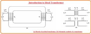
- The figure of ideal transformers can be seen here.
- The transformer in the above figure consists of Np turns at primary and Ns turns at secondary.
- The relation among the voltage given at the input vp(t) at the input side and in results it generates Vs(t) at other side.
![]()
- In this equation, the a is denoting the translation among the primary and secondary winding
a=Np/Ns
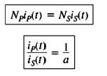
- The relation between the current ip(t) passing in the primary windings and current is(t) at secondary windings.

- The equation of phasers parameters for ideal transformer is mentioned here.

- Note that the phasor angle of Vp voltage is like the angle of Vs and the phase angle of primary current Ip is like the phase angle of secondary winding Is.
- There is a or turn ratio that shows disturbance for values of voltage and current not at their angles.
- All the above equations explain the expression among the magnitudes and angles of voltage and current at primary and secondary windings.
- The primary circuitry of voltage is positive for a certain point of windings. In case of a practical transformer, it is certain to explain the polarity of the secondary windings in the case of an open transformer.
- To minimize this factor there is dot conversion used in the transformer.
- The dot that exists at every point of windings in the above diagram explains the polarity of the voltage and current at the secondary sides of the transformer.
- The expression is explained here.
- If the primary voltage has positive values at dot point side of windings according to non dot point then the secondary voltage is positive at the devoted side. Voltage polarity is similar according to the dots at every side of the core.
- if primary current at the transformer moving towards the dot point the primary side the secondary current moving out from the dot point secondary windings.
Ideal Transformer Power
- The power given to the transformer through primary circuitry is mentioned in this expression.
![]()
- In this equation, θp is the angle between the primary voltage and Ip. The power is given to the transformer secondary circuitry at its output given through this expression.
![]()
- In this equation, θs is the angle among the secondary side voltage and secondary side current..
- As voltage and current angles are not disturbed through ideal transformer θp-θs=θ
- The primary and secondary coils of ideal transformer show similar P.F.
- Here question arises how power goes to the input side of ideal transformer then the power getting at the second part?
- It is certain to measure a it from the basic application of voltage and current expression shown
- The power equation of transformer is
Pout = Vsls cosθ
- If we use the turn ratio equation then ahs
Vs = Vp /a and Is = alp
Pout= Vp/a (alp) cosθ
![]()
- So the output power of the ideal transformer is like to its input power.
- A similar equation used to reactive power and apparent power of ideal transform

Impedance Transformation of Transformer
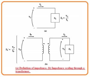
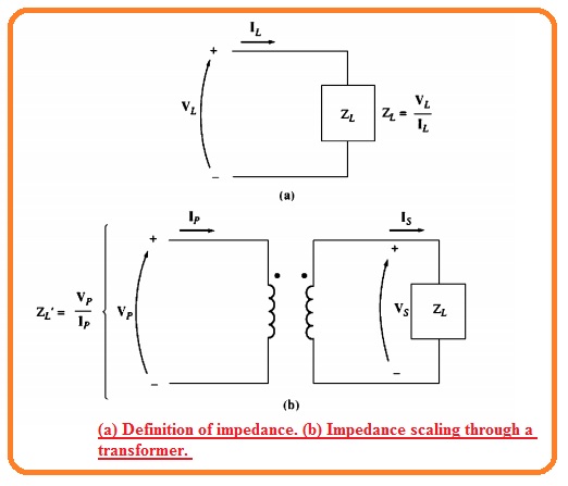
- The impedance is the ratio among the phasor voltage passing through any module and current about it.
ZL=VL/IL
- There is a good feature offered by the transformer because it varies voltage and current that results in the change in impedance.
- For practical understanding look at shown diagram
- If the secondary side current is denoted as Is and secondary voltage as Vs then impedance expression is mentioned here.
- ZL=Vs/Is
- The apparent impedance of the primary circuitry is mentioned here.
Z’ = Vp/Ip
- The value of primary voltage is given here.
- Vp = aVs
- The primary current is mention here.
- Ip=Is/a
- The equation of apparent impedance is given here.

Circuit Analysis having Ideal Transformer
- If circuit comprising ideal transformer for measurement of the value of the current and voltage shift part of circuitry at other side of the transformer through equivalent circuitry having the similar features.
- As the circuitry is moved to another part there is will be new circuitry created that has new values of current and voltage.
- At the part of a circuit which not varied the result will be accurate parameters of current and voltage real circuitry.
- So the turn ratio of transform is used to find the voltage and current at the second side of the transformer.
- The procedure of varying the one part of the transformer through its resultant at another part of voltage is determined as referring the ist side of the transformer to other.
So that is a detailed post about ideal transformer if you have any further query ask in the comments. Thanks for reading have a nice day.


