 Hello, readers welcome to the new post. Today we will discuss What are the design Principles of 3D printing. 3D printing also called additive manufacturing is the manufacturing of 3D objects through the use of CAD models or digital 3 dimension models. There are different processes involved in this technique where materials are deposited and connected and solids are made through computer programming and material are configured in layers structured.
In the 1980s 3D printing technique was used for the creation of functional or aesthetic prototypes and for rapid prototyping. In 2019 accuracy reputation and material range of 3D printing are increasing to make some three-dimensional processes that have important for industrial production technology which is known as additive manufacturing. Its main benefit is that it helps to make complicated desing and shapes that are not easy to make by hand. Fused deposition modeling that uses a continuous filament of thermoplastic materials is a common type of 3D printing used. In this post, we will cover the details of 3D printing and learn the design Principles of 3D printing. So let’s get started
Introduction to 3D printing
- 3D Printing is commonly known as the additive manufacturing process to make 3D objects through digital file applications
- The additive process used to make 3D-printed objects. In the additive process, objects are made through a combination of layers till the last assembly of the product.
- The layer of objects looks like the sliced form. This technique is the opposite form of subtractive manufacturing is cut into pieces of metallic material or plastic through a milling machine use
- 3D printing helps us to make complicated desing through the use of less material with the latest techniques
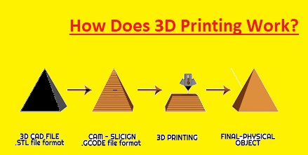
How Does 3D Printing Work?
- On the basis of ISO 3D printing has been 7 types and every type of 3D printing has different operations. The creation of 3D objects takes different times on the basis of 3D printing types, product structure, and material type. The time taken by the printing object depends on the basis of the desing.
PBF 3D Printing
- The powder bed fusion or PBF through the use of an electron beam or laser fuses certain areas of the powder bed to make layers
- These layers are created in sequence or consecutive. PBF consists of the sintering or melting process through basic operations that are the same. Firstly recoating roller or blade positioned an accurate layer of powder on the built structure. After that surface of the powder bed gets scanned through a heat source.
- This source enhances the temperature of particles to bind certain areas.
- When the layer is scanned through the heat source area suggests repeating the process is to make another layer. The resultant product is a structure having fused parts through having not to effect on the powder surrounding. After that combination goes to retrieve the complex structure.
- Powder bed fusion has many standard printing techniques that are SLS and DMLS
VAT photopolymerization
- VAT photopolymerization uses two methods DLP and SLA. They make components single layer at one time through the use of a light source to selectively cure liquid materials stored in a vat known as resin.
- While SLA depends on a single-point UV source or laser to cure liquid. Extra resin is removed when objected printing is completed after that products must be exposed to light to increase strength.
- These techniques are the best option for output that need a high level of accuracy since they made products with great finishing. DLP and SLA are well-used for prototypes
- This technique is brittle somewhat creating a suitable functional prototype.
Binder jetting
- Binder jetting operates through the deposition of an accurate layer of powered material like polymer sand ceramic or metal on the structure. hen print head deposited adhesive was applied to bind these components. These components are created through a layered structure.
- A metallic portion is thermally sintered or infiltrated through metallic material that has a low melting point like bronze. Components created with ceramic or polymer can be structured through the use of cyanoacrylate adhesive.
Material jetting
- Material jetting is like inkjet printing. Through it used print heads were then inserted ink on papers for the deposition of layers of materials.
- Every layer is completely finished before the creation of another layer. Material jetting depends on the structure they can make through the use of water-soluble substances which can be washed after the creation of the structure
- This accurate process and used for cration of complete colored parts through the use of different materials.
Fused deposition modeling
- The FDM or Fused deposition modeling uses a heated nozzle to add the filament spool in the extrusion head. The extrusion head enhances the temperature of the material softening it to place in a certain place to cool it.
- Once the material layer is made the built platform descends and makes for a new layer to create
- This process called material extrusion results in low lead time and is less expensive. Though it is a good structure and smooth finishing after post-processing.
Sheet lamination
- Sheet lamination has two types UAM and LOM. UAM uses less energy and temperature and operates by joining thin metallic sheets through the use of ultrasonic welding.
- UAM has less energy and temperature needs and operates through a combination of thin metallic sheets through the use of ultrasonic welding.
- It operates through many metallic materials like stainless steel, titanium, and aluminum.
Direct energy deposition
- In this technique lasers, an electron beam, and an electric arc are used to focus thermal energy for fusing powder or wire feedstock to be positioned. This technique operates in a horizontal fashion to make layers that are then stacked in a vertical fashion to make parts.
What are the design Principles of 3D printing
- In this post, we will discuss the 3D printing desing guidelines used at JLCPCB. JLCPCB is the best PCb service provider company that provides PCB and related products in one platform form with great quality and reasonable prices.
- The PCB order process is simple. They have an instant quote online and a self-service platform that takes you minutes to upload your files and order your boards. They are fully transparent in our operations, you can know everything about your orders in real-time as every step can be tracked and reported on JLCPCB.
- Their customer support team is available 24 hours a day from Monday to Saturday via phone, live chat or email. Every customer support is trained and qualified. You can always get effective help and support from them.
- About 10% of the data packages they receive have elements or features that need to be clarified. A lengthy process of technical issues will negatively affect the delivery and the overall cost. Our technicians work systematically to clarify the ambiguities in your specification. This way of working is more efficient and helps to complete the process of engineering questions faster and reduces the time required for production.
- So let’s discuss 3D Printing Design Guidelines offered by JLCPCB
Wall Thickness
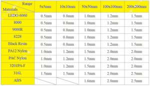
- The three-dimensional printing technique required alcohol cleaning, and supported the removal, grinding, and sandblasting. Therefore model specific strength and thickness define the strength of parts
- In 3D printing, wall thickness defines the distance between one layer of part and the opposite sheer surface. The part created through 3D printing consists of the least wall thickness which depends on the net size. For guidance, JLCPCB recommends that we can enhance wall thickness when we scale the desing to a larger size.
Embossed and Engraved Details
Minimum Embossed Detail
- Minumm embossed details are discussed here
- LEDO6060/8000/9000R/8228/Black Resin : 0.5 mm deep & 0.5 mm wide
- PA12: 0.5 mm deep & 0.5 mm wide
- PAC: 0.8 mm deep & 0.8 mm wide
- 3201PA-F : 0.8 mm deep & 0.8 mm wide
- ABS: 1.0 mm deep & 1.0 mm wide
- 316L: 1.0 mm deep & 1.0 mm wide
Minimum Engraved Detail
- LEDO6060/8000/9000R/8228/Black Resin: 0.5 mm deep & 0.5 mm wide
- PA12: 0.5 mm deep & 0.5 mm wide
- PAC: 0.8 mm deep & 0.8 mm wide
- 3201PA-F : 0.8 mm deep & 0.8 mm wide
- ABS: 1.0 mm deep & 1.0 mm wide
- 316L: 1.0 mm deep & 1.0 mm wide
Thread design
- There are 3 main facts that have 3D printing of non-standard threads first one is thread pitch and Helix angle


- The clearance fit of thread is required to denote model clearance. If there is no clearance fit in the desing it will not be able to assemble. The least standard screw is M6
Model Clearance
-
Clearance between parts that will be assembled together
- Modules can be printed to assembled as they fulfill the leat clearance as shown here


Clearance between moving parts
- The least clearance between tow moving connections is shown here


- This is the least clearance of simple structures that is not used for all structure
Escape Holes
- Hallo designs required escape holes therefore extra material can escape when 3D printing is done. Mostly printing services use printers and printing techniques which need at leat one escape hole

- The escape hole has a minimum dia of 2.5 mm
- Two escape holes are needed when the escape hole dia is less than 3millimeter, the resin will not flow and the cavity will not be cleaned and the part can crack after some time.
- The size and quantity of escape holes must be defined on the basis of model size and structure
- The support in the cavity is not completely eliminated till the escape hole is designed in a larger size
Holes design
- The relationship between aperture (Φ) and hole depth (h):

- When model is designed through micropores and deep holes then refer the above-shown standards
Small column design
- The relationship between column diameter (D) and column height (H):

- When the model is created through the position column then define these standards
Special-shaped model
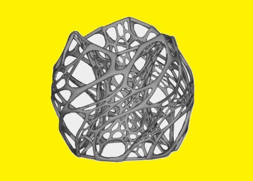
- The certain-shaped model is a hollow structure that has larger spaces as seen here
- If it is designed as a certain shaped part and fulfills the printing needs certain charges
3D Printing Tolerances
- Resin materials: ±0.2mm or within 0.3%
- Nylon materials: ±0.3mm or 0.4%
- 316L : ±0.2mm or within 0.3%
- ABS : ± 0.3mm or within 0.4%
Tolerance changes over time:

Multiple same-parts design
- A maximum of ten pieces same small parts can be supported in one file but all distinct parts must be attached and joined in one larger part to process and the wall thickness of connection areas must be less than 1.5mm.
- Also, note that FDM with ABS materials and SLM with 316L material are not supported in this method
That is all about the What are design Principles of 3D printing all details has explained. IF you have any query ask here


