An inverter is the main part of electronic circuit projects that convert DC power to AC through the following solid-state circuits. Similar voltage source inverters also perform DC to AC conversion. A voltage source inverter other name is voltage fed inverter. VSI is basically a combination of a DC power supply, transistors of different types that perform the switching process, and a capacitor that removes signal fluctuations and provides a filtering process.
In this post, we will cover detailed features of VSI and its related factors. So let’s get started.
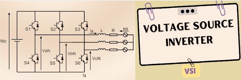
What is a Voltage Source Inverter?
- The voltage source inverter is an electronic circuit or device that operates according to the inverter working principle for DC to AC conversion.
- It operated with a constant power source to provide a stable output voltage supply.
- VSI works without an output current sensor, and the control system uses a voltage feedback signal to provide an accurate output signal.
- So voltage source inverters provide high-speed response and good performance. VSI structure comes with different electronic components such as an IGBT inverter, MOSFET transistor, PWM circuit, and filter circuits.
Voltage Source Inverter Parts
VSI comes with different parts that make a complete circuit assembly for performing work.
DC power source
- DC sources provide stable DC voltages for performing inverter functions. DC supply can be gotten from a battery and other sources. For solar power systems, 6V and 12V batteries are used.
Switches
- switching circuits made with different semiconductor components, like IGBT and silicon-controlled rectifier circuits.
- These switches on the DC voltage supply are for producing an AC signal. Power semiconductor switches come in 3-phase bridge circuits for producing three-phase AC.
Inverter bridge circuit
- It has many switches connected in a bridge-like design that converts DC to AC.
Control Unit
- Control units manage output voltage and frequency through managing switching features. It uses PWM digital signal processors for accurate control.
Filters
- Output obtained at the bridges comes with pulsation for making a smooth output signal; inductors and capacitors are used as a filter. so a pure AC output is obtained with less distortion.
Protection Circuitry
- The inverter needed different protection circuits that are safe from different conditions. Commonly used circuits are thermal protection modules and overvoltage and overcurrent circuits.
Components:
- Overvoltage protectors, overcurrent andprotection devices.
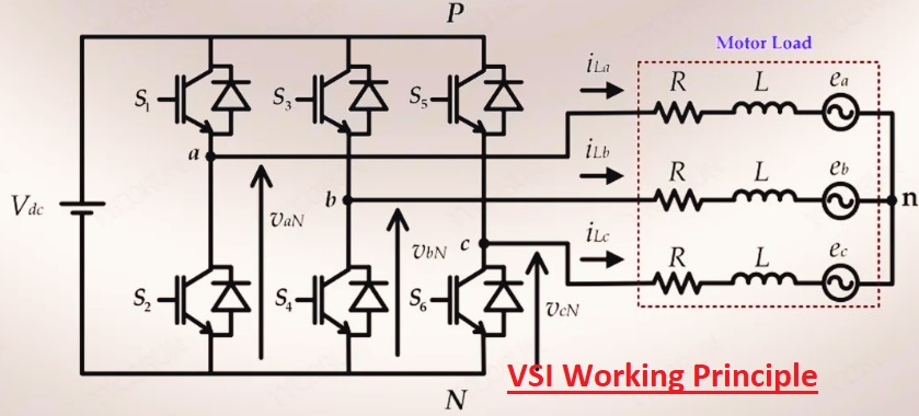
VSI Working Principle
The main working of VSI is to convert DC voltage into AC voltage. This process is performed through high-switching devices that are connected with a DC source and provide an AC signal to the load.
The detailed working process is explained here.
DC Input Supply
- DC supply at input taken from DC voltage source given to inverter
Switching components
- • The inverter comes with different switching components, such as MOSFET and IGBT in a bridge-like assembly for converting DC to AC, and delivering it to the load.
Switching Control Circuit
- • The inverter controller causes modulation through PWM to regulate output AC volts and also amplitude.
Filtering circuit
- • The filter circuit removes harmonics of the AC output by making a circuit with an inductor and a capacitor and gets a pure AC signal.
power to load
- Pure AC volts are provided to a load that operates different devices, such as motors and other AC-based devices
Voltage Source Inverter Features
The main features of the voltage source inverter are as follows:
accurate control
- VSI provides accurate output voltage and frequency control and provides voltages for the required voltage demand.
Efficiency:
- It shows high efficiency for the transformation of DC to AC power, reducing energy losses when conversion occurs.
Versatile design
- VSI performs different applications such as operating small loads to industrial machines.
Compatible design
- They have features to integrate with different power supplies like solar panels, DC sources, and batteries.
Single Phase Half-Bridge Voltage Source Inverter
- Here, you can see the circuit of single phse half bridge voltage soruce inveter.
- In the circuit, there is a TX thyristor that operates for half the time period, and the other TY operates for the other half of the output signal.
- diodes in circuits connected with antiparallel combination to thyristors that provide current flow when the main thyristor is not working.
- DX diode operates for positive voltage and negative current, and diode Dy operates for negative voltage and positive current.
- This feature is applicable for non-resistive loads where the diode operates, and power is delivered back to the DC source, and diodes Dx and Dy operate as flyback diodes.
- thyristor operated with a gate. That is, it operates for the time when the gate pulse exists and is commutated until the pulse operates.
- Below, you can see the gate signal for thyristors TX and TY with the output signal of the inverter shown.
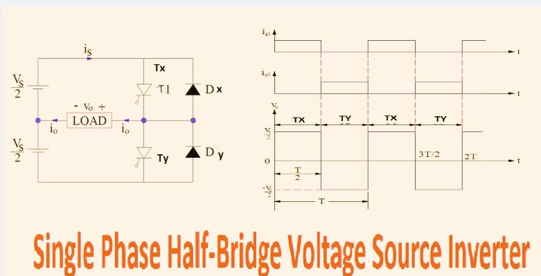
Here, observe that for the period of 0 < t ≤ (T/2), tx operates in this time, and the load is connected with Vs/2 on the upper part of the circuit, and the output voltage for this time is Vs/2.
- ig1 is disconnected for time T/2, thyristor Tx becomes off, and ig2 is now given to ty, and it operates. In results, load operates for -Vs/2 on the lower circuit part. output voltages are -Vs/2
- The output signal is an AC square wave whose frequency is 1/T Hz and amplitude is Vs/2. Frequency is regulated with period, T.
- This circuit needed three 3 DC supplies. while the output is half the magnitude of the input signal, which limits its operations. For managing this limit full bridge circuit is used
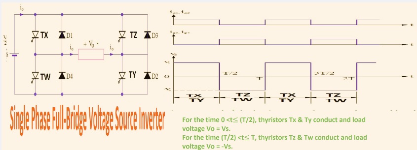
Single Phase Full-Bridge Voltage Source Inverter
The circuit diagram of a single-phase FB-VSI with a load is shown below:
- This circuit assembly comes with 4 thyristor TX, TY, and TZ tw, with four diodes, and uses a two-wire DC source and load.
- diodes connected in anti-parallel connection to the thyristor, and current flows when the main thyristor is off.
- When diodes conduct energy given back to the DC supply, all 4 diodes are flyback diodes.
- Each thyristor operates when a gate signal exists, and when the gate signal is off, the thyristor stops working.
- The thyristor is triggered diagonally for half the period; thyristors tz and tw work, and for the other half, signals tx and ty operate.
- That means two thyristors work for half the performance
The gate signal and the output voltage are shown below:
Voltage Source Inverter Types
- VSI comes in different types according to output signal and modulation methods. basic types of VSI are as
Square Wave VSI
- This type of VSI produces a square AC signal through switching DC volts on and off at a certain frequency. It is a simple design and low-cost circuit. with fewer components for circuits.
- But its high harmonics make low-quality signals and cause signal distortion, which makes it less effective.
- Its uses are in heating elements where signal quality does not matter.
Modified Square Wave VSI
- This inverter generates an almost sine wave through using voltage level. Its main feature is better signal quality than the previous type, with a low-cost design.
- Its common uses are in motor drivers and lighting circuits, where a quality square wave is needed.
- Its limitations are high harmonics in the signal compared to a sine wave inverter, and it is not used for sensitive design devices.
Sine Wave VSI
- It causes a pure AC signal that is preferred for different devices. with fewer harmonics and preferred for inductive loads.
- It is part of UPS circuits, medical devices, and projects that need high AC.
- It is a complicated design and high cost since it needs a filter and control of demand. It also uses larger components.
Pulse Width Modulated Inverter
- It operated with PWM for providing high-frequency switching that has a clear sine wave. It comes with pure sine with low harmonic distortion.
- It provides control for voltage and frequency.
- Its operations are highly efficient with a good handle, so it is used for VFDs, renewable energy systems, and motor control circuits.
Application of voltage source inverters
voltage source inverter is used for different applications since it provides different features
Renewable energy sources
- VSI main component for converting DC output obtained at solar panels to AC power for operating loads and providing power to the grid
Motor drives circuits.
- It is used for variable frequency drives used for motors and gives accurate control for torque and motor speed.
(UPS) circuit
- VSI provides an AC power supply in UPS circuits when the main supply is off and operates different loads.
Portable power sources
- When we are on long drives and in areas where a power supply does not exist, voltage-source inverters convert the battery’s DC supply into AC power for operating AC devices.
Variable Frequency Drives (VFDs)
- VFD also operated with VSIs that regulated speed and motor torque through controlling frequency and voltage supply. that causes proper process control and longer working life of devices. such as conveyors, compressors, and machine tools
HVAC Systems
- For the HVAC system, vsi provide regulation of compressor speed and fans through accurate energy usage, and increases system working performance.
Electric Vehicles (EVs)
- VSI is also employed in EVs for providing working of the propulsion motor, accurate speed control, high torque efficiency, and good vehicle performance.
- So its uses are in auxiliary power systems and regenerative braking systems.
Industrial Automation Systems
- VSI provides accurate motor control for high-speed manufacturing processes with accuracy. So part of the CNC machining system, robots, and automated assembly lines
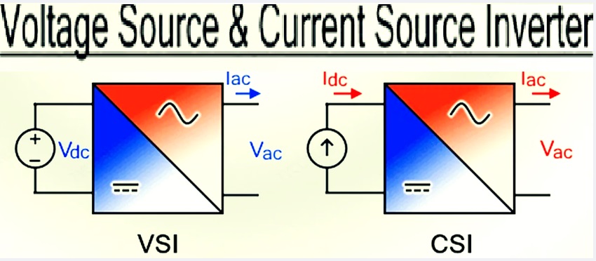
Voltage source inverter vs current source inverter
The basic differences between voltage source inverters and current source inverters are as
- Both working with different techniques for voltage conversion, like the voltage source inverter operated with semiconductor switching modules that transform DC into AC and the current source inverter that transforms DC into AC through power control circuits and filters
- They use different controlling techniques, such as a voltage source inverter work with the pulse width modulation control process, and the current source inverter follows the current control method.
- VSI output is a pure sine wave, and the current source inverter wave has good current control and overcurrent handling.
- Both have different applications, such as voltage source inverters for parts of high-power loads, like medical devices and computers, and current source inverters preferred for applications where high power is needed, like motors and industrial robots. and electric-based vehicles
Voltage source inverter vs current source inverter – which is better?
Voltage source inverter (VSI):
- VSI is used since it provides high efficiency and has a versatile design. It causes modulation of DC input voltage for providing AC output and is preferred for different applications. Its accurate control for voltage and frequency makes it effective for different loads.
Current source inverter (CSI):
- CSI provides constant current at input terminals and performs AC output modulation with controlled switching components. CSI is part of motor drives and renewable energy systems.
- So, choosing between VSI and CSI follows these points.
For compact systems, battery-operated and portable devices use VSI.
For heavy industrial motor drive circuits, CSI is used.
| Features | Voltage Source Inverter (VSI) | Current Source Inverter (CSI) |
|---|---|---|
| Input | Constant DC voltage | Constant DC |
| DC Link Component | capacitor to maintain voltage | inductor for maintaining current |
| Switching Devices | IGBTs or MOSFETs | SCRs or GTOs |
| Output Control | voltage waveform | Controls current waveform |
| Complexity | easy to implement and control | complex control logic |
| Compatibility | resistive and capacitive loads | inductive loads |
| Harmonics | Voltage harmonics are higher | Current harmonics are higher |
| Regenerative Braking | complex to use | Easier to use |
| Cost | Lower due to simpler filter process | Higher since large inductors and complex control |
| Efficiency | higher efficiency | lower efficiency |
Conclusion
In different electrical and industrial applications, voltage source inverters are commonly used since they provide accurate control of the AC supply effectively. It is highly efficient and maintains power at different ranges, like renewable energy integration and motor drives for electric vehicles, and is employed for UPS systems.
FAQs
What is a voltage source inverter’s other name?
- Another name for a voltage source inverter, commonly used for power electronics circuits and causes operations of voltage control circuits
What is a solar inverter: a current source or a voltage source?
- A solar inverter is a voltage-source inverter that transforms the DC output of solar panels into AC power for operating different loads. VSI provides AC power according to the required voltage level with frequency.
Why is PWM switching used in voltage source inverters?
- PWM switching is used in voltage-source inverters since it has features for controlling output voltage and frequency through high accuracy. It helps to provide effective control to provide power for devices and through showing the required AC waveform.