 Hello guys, I hope you all are doing great. In this post, we will discuss Transformer Voltage Regulation and Efficiency. The transformer is an electric instrument that used to vary the power level. The voltage regulation of the transformer is a variation in the voltage value existing at the input and output of the transformer. It is generally used in the power system to discuss the percentage voltage differentiation among the no-load and full-load voltage.
Here we cover all parameters related to voltage regulation. So let get started.
Transformer Voltage Regulation and Efficiency
- As the real transformer consists of series impedance in it structure the output voltage of the transformer changes in the load though if input voltage has constant values.
- The easiest way to do a comparison transom through these features it is easy to explain the parameters known as voltage regulation.
- Full load voltage regulation is a term that do a comparison among the output voltage of a device given at no load to the output voltage in case of full load. The equation of voltage regulation is given.
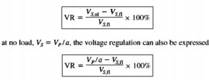
- If transformer circuitry is given in per unit system the voltage regulation will be.

- Generally, it is fine way to has smaller voltage regulation. In the case of ideal transformer, VR is zero it is not the fine way to get less voltage regulation so a high value of impedance and large voltage regulation are used to decrease the faulty current.
How to measure voltage Regulation
Transformer Phasor Diagram
- For measurement of voltage regulation of transformer, it is compulsory to observe voltage loss in the transformer.
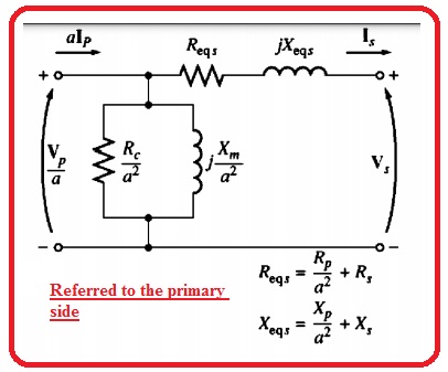
- assume the simple transformer circuitry shown in the below figure.
- The factor of excitation brach at transformer voltage regulation does not take into consideration. therefore the series impedance required to take into consideration.
- The voltage regulation of the transformer relies on at magnitude of these series impedances and at the phase angle of current passing in the transformer.
- The simple method to find the fact of impedance and current phase angles at transformer voltage regulation is to discuss the phasor diagram.
- In the phasor diagram, the phasor voltage is taken at an angle of zero degrees and other voltages and currents are compared.
- Through the application of KVL at the circuitry in above figure the primary voltage can be determined as.

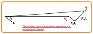
- The transformer phasor diagram is the explanation of the above equation.
- The diagram is shown below the phasor diagram of transformer working with lagging P.F.
- It is simple to observe the Vp/a>Vs for lagging loads therefore the voltage regulation at transformer having lagging loads shouls be larger over the 0.
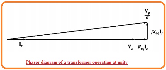
- The phasor diagram for unifying P.F can seen below.
- Here voltage for secondary is less than the voltage for primary. In result, voltage regulation is larger than zero.
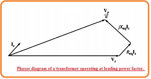
- Though for this time voltage regulation is less than for lagging current. If the secondary current is leading secondary voltage will be larger than the referred primary voltage.
- If it occurs transformer has negative voltage regulation
What is Transformer Efficiency
- Transformer operation can be analyzed at the base of efficiency. The efficiency of instruments is defined here
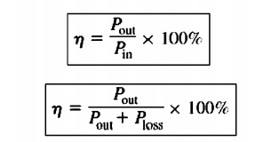
- The above expression used for motors and generators with that for transformer.
- The transformer equivalent circuitry creates efficiency to make measurements simples.
- So 2 categories of losses exist in the transformer.
- Copper losses These losses occur in the series resistance of equivalent circuit of the transformer
- Other losses are addy current and hysteresis losses.
- The power equation of the transformer is mentioned here.
Pout=VsIscosθs
- The efficiency of the transformer is given here.


