
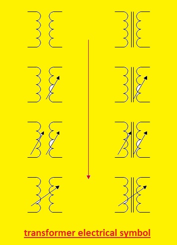
 All Types of Electrical Transformer symbols and diagrams. In the field of electrical engineering, transformers main components. Through the use of the phenomenon of electromagnetic induction, they are used for the transfer of electrical energy from one circuitry to another. There is different types of transfer used in electrical power systems based on construction and uses. Each has its own symbols and schematic diagram. Here we will cover the different transformer diagrams and symbols in this post. So let’s get started with Transformers Electrical Symbols
Introduction to Transformer
- A transformer is an electric device that changes the voltage level from high to low or low to higher. Based on the application, it changes voltage levels. Electrical engineers who are handling the transfer must know transformer symbols.
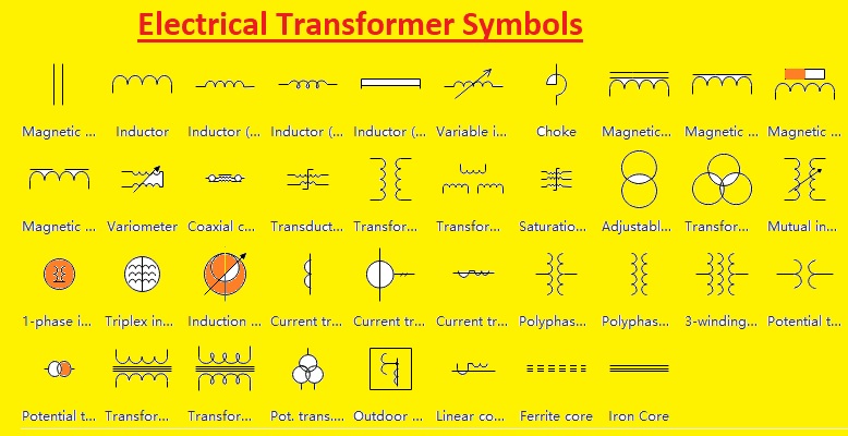
Electrical Transformer Symbols
- Transformers’ Electrical Symbols provide the function of devices and their work to make easy knowledge of their features and related parameters. Here you can see the common electrical symbols for transformers used in electrical diagrams:
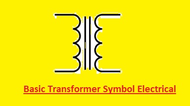
Basic Transformer Symbol Electrical
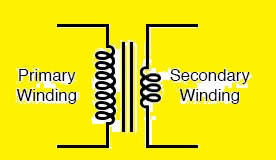
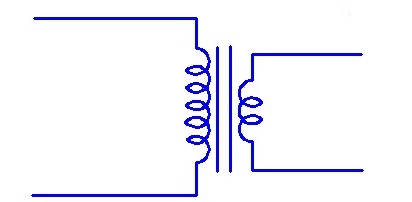
- In the basic transformer symbol electrical, primary and secondary coils are separated using dotted lines. The voltage supply is connected at primary windings and the load is at secondary windings
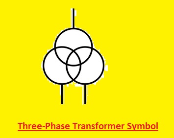
Three-Phase Transformer Symbol
- Three single-phase transformers are connected in such a configuration that makes symbols for three-phase transformers. Their primary and secondary windings are connected are in wye or delta configuration. The 3-phase transformer symbol can seen here
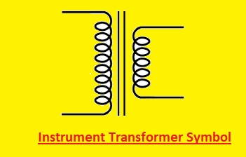
Instrument Transformer Symbol
Instruments transformers are used to measure the value of current and voltage of circuits. Here you can see the current transformer and voltage transformer symbol
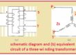
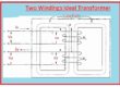
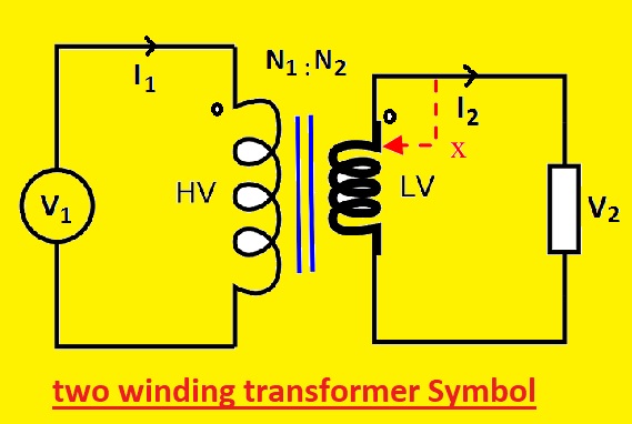
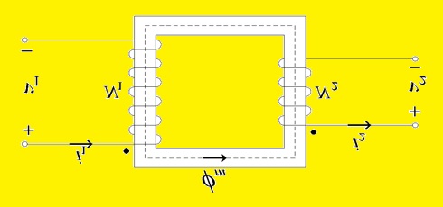
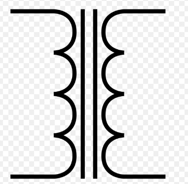
Two Winding Transformer
It is a general transformer made with two winding connected through changing magnetic flux.
Single Phase two Winding Transformer
This transfer has two windings and both primary and secondary are used with a single phase. it comes with two primary and two secondary terminals.
Single Phase Separate Winding Transformer
Here you can see single-phase transfer symbol that comes with separate windings for primary and secondary terminals. Double dashed line denotes two terminals for each winding.
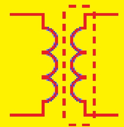
Shielded Transformer
Shielded transfer comes with an electrostatic shield between primary and secondary winding that save transfer of high spikes of voltage and frequency noise. The shield is grounded and capacitance between the shield and primary winding saves noise transfer in the result of high-frequency
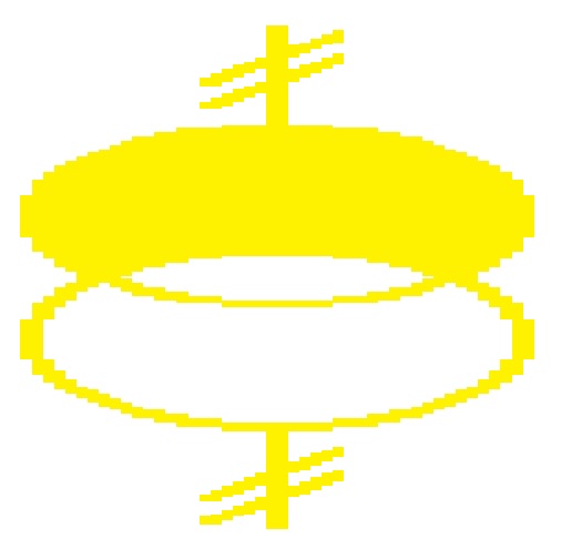
Moving magnet Transformer
The voltage in this transformer winding is induced through the movement of a magnet near the winding. The phone cartridge uses MM transformer and it transforms the movement of the stylus into an electrical signal through a moving agent connected with tips.

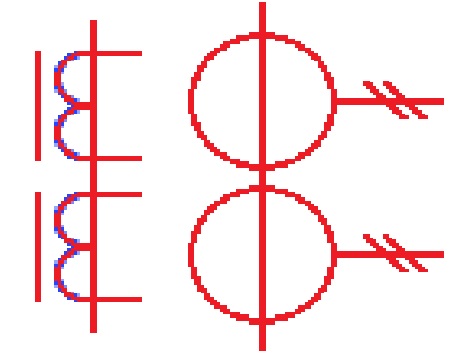
Dual Core Current Transformer with Two Secondary Lines
It comes with two crosses each for the single secondary winding. Every winding provides a different turn ratio for access to two different current ratios on each single winding.
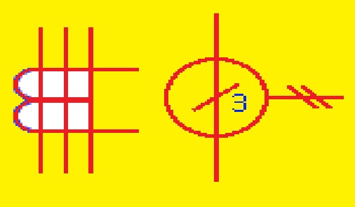
Current Transformer with 3 Conductors
This transformer is also called CBCT or core balance curent transformer. it has three conductors running through cors. The total vector cusm of current in the normal state is 0. If there is an earth fault current difference comes through CBCt which is connected with the alarm system.
Center Tapped Transformer
The center-tapped transformer comes with a tap point in the middle of the secondary winding that helps to access a half number of turns in the secondary winding. The voltage between the center tap point and any endpoint of winding is half of that winding.
Transformer with Winding Polarity
The winding polarity in the transformer is denoted with a dot convention. if current enters the primary dotted terminal voltage induced in the secondary dotted terminal is positive. If curent left primary dotted terminal voltage induced in secondary dotted terminals is negative. They are used for connection transformation in parallel for increase the capacity.
Single Phase Transformer Symbol
- single-phase transformer is a very commonly used type of transformer. It has two windings primary and secondary windings with a magnetic core to make a symbol of the transformer. The secondary windings are connected with the load and input supply with primary windings. In the symbol, there is a single line that has an arrow or dots connected to the voltage source is a symbol of primary windings. Two parallel lines that are added arrows end connected to the load are called secondary windings
- Here is the single-phase transformer’s symbol.
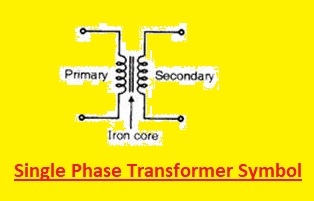
- Two dots in the symbols on windings are directions of current flow. The step-down transformer is used where current flows from primary windings to secondary for voltage to decrease. For a step-up transformer, current flows from secondary to primary windings, and voltage increases.
- A single-phase transformer diagram shows the symbol and details the transformer’s ratings, which are primary and secondary windings power ratings, and current.
Iron Core Transformer Symbol
The iron core is used for the creation of an iron core transformer that increases magnetic characteristics and efficiency. The iron core exits at the midpoint of the iron core transformer which has single phase transformer symbol
A transformer with an iron core is shown here
- This symbol comes with a magnetic core in mid of the windings and a line that comes with an arrow or dot marking is connected with a voltage supply to show primary windings. Two parallel lines that are dots connected with load and secondary windings
- The magnetic core is shown in the middle of the symbol as a rectangle. The primary function of the core is to increase the magnetic features of the transformer by decreasing flux leakage and increasing magnetic among both windings
Ferrite Core Transformer Symbol
A ferrite core transformer symbol can seen here
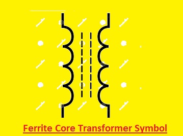
Here symbol has a ferrite core in the midpoint if two windings first one is primary and the second one is secondary. The single line that comes with an arrow or dot connected to the voltage source is the primary windings. Two parallel lines that have dots showing endpoint connected with the load as secondary windings
A rectangular shape in the middle of the transformer symbol symbolizes the ferrite core.
Air Core Transformer Symbol
In this type of transformer, an air core is used as a medium instead of a magnetic core for magnetic flux. A transformer with an air core has a very different symbol from one with an iron or ferrite core.
The following is the air-core transformer’s symbol:
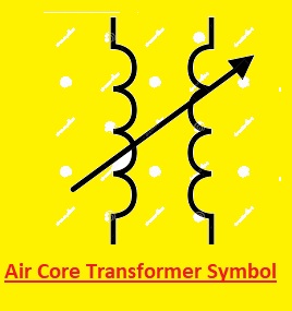
In this symbol, there are two windings and the middle has an air core. The single line having dots is connected with the voltage supply, and two parallel lines with dots connected with the load are secondary windings.
The magnetic features of the air-core transformer are less than an iron-core or ferrite-core transformer due to the absence of a magnetic core. Air-core transformers are not effective for high-power applications. However, due to less losses and good efficiency, they are used in radio frequency (RF) applications.
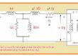
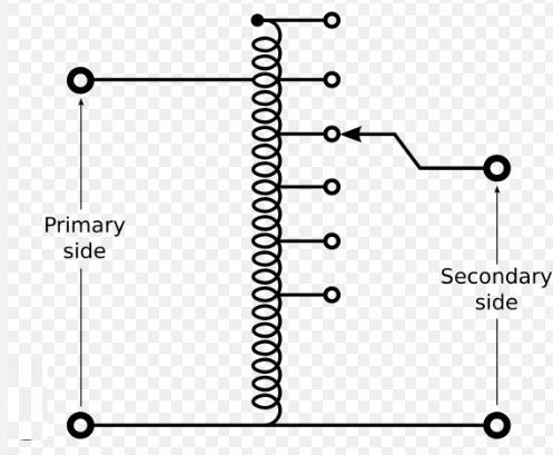
Variable Transformer Symbol
The output voltage of this transformer called variac or autotransformer, can be controlled by turning a dial or knob. The 2nd arrow denotes the variable putout voltage configured to the conventional transformer symbol to represent a variable transformer.
A variable transformer has the following symbol:
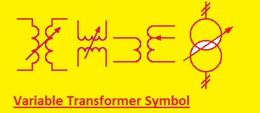
The primary and secondary coils of the symbol are shown, also moving sliders in the center of the symbol. The arrow directed to the curved line in the middle of the transformer symbol shows the variable slider. This arrow shows variac’s moveable contact, which can be varied for voltage change. The curve lines denote variac’s resistive component, which makes smooth and correct voltage regulation.
Step Down Transformer Symbol
A transformer type called a step-down transformer lowers the input voltage to raise the output voltage. A step-down transformer has fewer turns on the secondary coil than a conventional transformer, yet both transformers have the same symbol.
The symbol for a step-down transformer is shown here
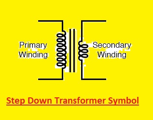
We can observe that, the symbol has two coils, primary and secondary, with the secondary windings having fewer turns than the primary windings. The primary coil is represented by a single line that usually has a dot or arrow indicating the end that is connected to the voltage source. The secondary coil is represented by two parallel lines that also have dots or arrows indicating the end that is connected to the load.
The fewer turns on the secondary coil of a step-down transformer result in a lower output voltage compared to the input voltage. For example, a transformer has 120 volts at the input and 12 volts at the output will have10:1 turn ratio, which means that the primary winding has 10 times more turns than secondary windings
Step-Up Transformer Symbol
This transformer increases input voltage to high voltage at output. The symbolic representation of this transformer is like that of a conventional transformer but with higher numbers of turns on the secondary windings.
symbol for a step-up transformer:
In this symbol, two windings primary and secondary wings having secondary have larger tuners than primary windings. The primary windings are shown as a single line that has dots connected with the voltage supply. These windings are denoted as two parallel lines and connected with the load.
The larger turns at secondary windings have a higher voltage than the input voltage. A transformer with 102 volts at the input will have 240 vols at the output with a ratio of turn 1:2, which means secondary wings are double the first windings
Autotransformer Symbol
In this transformer, there is one winding used as primary and secondary. The symbol for an autotransformer is like the conventional transformer; it comes with one winding and two coils
Here’s the symbol for an autotransformer:
the symbol has single windings with different taps of different lengths. the autotransformer comes with rating data of transformer windings like voltage power, and current ratings having a ratio of the transformer. This transformer can have many taps with coils having voltage variations
These transformers are used in voltage regulation projects such as in voltage stabilizers, variable speed drives, and audio devices.
Isolation transformer Symbol
- An isolation transformer comes with a portion between input and output circuits without any connection between physical or direct. The symbol for an isolation transformer is like the normal transformer with more windings for isolation
- the symbol of an isolation transformer is shown here
- In this figure are two windings that are not connected in any direction. With a primary connection with the voltage supply, primary and secondary windings are found by dots. isolation windings sow dotted lines.
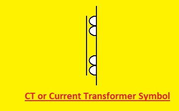
CT or Current Transformer Symbols
- Alternating current (AC) or high-frequency current is measured using a CT transformer. The current transformer symbol comes with secondary windings that have fewer turns than primary windings and have the same symbol as a conventional transformer.
- CT symbol is shown here
pt symbol electrical or Potential Transformer Symbols
- This transformer is used for voltage measuring the circuit through making high to low and due to the protection purpose, they are called PT or voltage transformer, since it steps down high voltage levels to a lower, controllable voltage value. its symbol like the normal transformer,
- Here is the diagram of a potential transformer:
- These transformers are used to measure the correct voltage value like in metering devices, protective relays, and power monitoring systems.
Symbol of Voltage Transformer
- These transformers are used to protect the system from high voltage and are called VT or potential transformers, and it step down the high voltage to low voltage. it is like the conventional transformer, but with difference is that it has lower voltage ratings
- Listed below is the voltage transformer’s symbol:
AC Transformer Symbols
- This transformer is used to work with AC power supplies so it is known as AC transformer. its symbol is like the conventional transformer
- The following is the icon for an AC transformer:
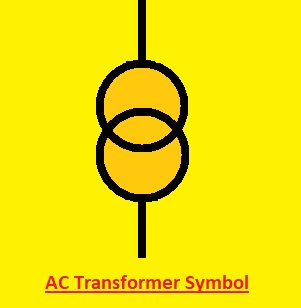
- An AC transformer comes with primary a secondary windings and a transformer core that can seen as a rectangle-like layout or any other type of shape. These transformers do not work on a power source
- These transformer used in motors light systems and power supplies. They are also used in AC power distribution systems that vary the voltage level according to project demand
Power Transformer Symbol
- With changes in voltages, this transformer also transfers the power from one circuit to another circuitry. Like the symbol of a conventional transformer, this transformer comes with some more symbol configurations to show the different parameters
- Below is the power transformer’s symbol:
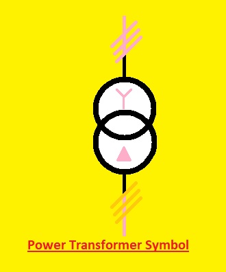
- The primary secondary and transformer core are part of this transformer. Each winding has several turns on the windings and there can be extra symbols to show the phases and voltage levels of the transformer
- These transformers are used for transmission, power generation, and distribution projects. These devices are used in larger-scale systems where high voltage is controlled and transmitted.
Distribution Transformer Symbol
- The power or voltage value that we get is a step down that certain level through a transformer called a distribution transformer. The symbol of this transfer is like eh normal transformer with some more pictures that define different parameters of the transformer
- A distribution transformer is represented by the following symbol:
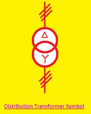
- This symbol has primary secondary and windings and core of transformed with some extra symbols to show the phases and windings configuration of the transformer.DT is mentioned in the core of transformed to define that it is a distribution transformer.
- It is used in the power system to decrease the voltage level to a certain value before sending it to the user’s end. commercial, and residential areas have these transformers
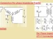
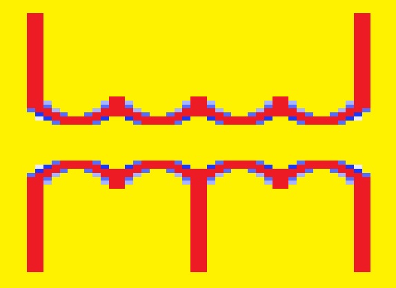
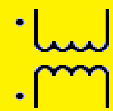
Electrical Transformer Diagrams
Transformer diagrams are symbolization representations of components of a transformer and their connections here you can see different transformers with their electrical diagrams
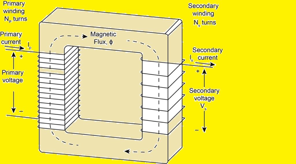
Single-Phase Transformer Diagram
In single-phase transformer, there are main cores primary and secondary windings. Secondary windings is connected with load and primary to input source
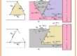
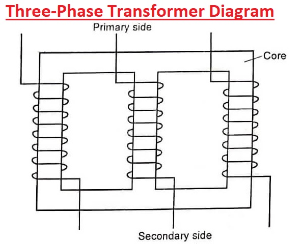
Three-Phase Transformer Diagram
Three single-phase transformers are configured in such a way that make a three-phase transformer. Normally primary and secondary windings wye or delta connections. An example of a three-phase transformer diagram is shown in the image below:
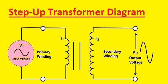
Step-Up Transformer Diagram
A transformer that increases the voltage level from the primary side to the secondary side is called a step-up transformer. A common step-up transformer electrical diagram is seen here
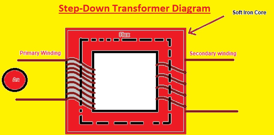
Step-Down Transformer Diagram
Transformers that decrease the voltage level from the primary side to the secondary side is called step-down transformers.
step-down transformer diagram is shown in the image below:
What is a Transformer Used for?
An electrical device called a transformer converts the electrical power value or voltage value between two circuits. Its works are based on electromagnetic induction that helps transfer power from one circuit to another by varying the magnetic field. They are used for changing the voltage level according to circuit need, for this turns ratio is varied according to voltage value.
They are used in generation systems and also for power transmission. In generation systems, they are used to increase the voltage lev level to transmit longer distances, and in distribution systems, it lower the voltage level to provide the required voltage according to their appliance’s need. They are also used in different electronic devices and projects that need lower voltage values to operate different components.
They are also part of induction heating, welding, and battery charger circuits
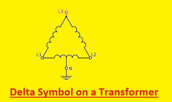
What is the Delta Symbol on a Transformer?
A three-phase transformer with a delta connection on the primary side is shown. There are three primary windings of the transformer are connected in a triangle layout that makes a delta connection and secondary windings are connected in a star (Y) or delta arrangement.
The delta connection comes with a higher current and voltage ability than a single-phase transformer used in industrial areas where high power is handled. it is more effective than a single-phase transformer as less material and copper are used to handle the same power
In electrical circuit and wiring diagrams, the delta symbol is used to show the three-phase transformer with a delta connection. The primary winding so these transformer are shown as L1, L2, and L3 written on each corner.
Conclusion: transformer electrical symbol
In conclusion, transformers are the main part of our electrical system to provide different power values according to load demand different types of transformers used for their different features and construction parameters come with different symbols and circuit diagram
Read Also:
- 30 Amp Wire Size: What AWG Wire You Need?
- 125 Amp Wire Size and Breaker Guide
- 60 Amp Wire Size – Which AWG is Best for 60 Amp Breaker
- What Size Wire for 200 AMP Service Underground
- What Size of Wire Do I Need for a 100 Amp Sub Panel?
- How to Replace Doorbell Transformer With Diagrams
- What is Auto transformer Starter
FAQs
Q1. Define transformer, and how does it work?
- A transformer is an electrical device that works on electromagnetic induction to vary the voltage level from one to another according to need. It comes with two windings primary and secondary and core winding. The voltage source is connected to a primary side and loaded to secondary windings
Q2. Write different types of transformers.
- Transformers come in different types based on structure, and circuit design such as instrument transformers, three-phase transformers, and autotransformers.
Q3. What is the purpose of transformer symbols and diagrams?
- Transformer functions and operations are denoted with symbols and diagrams, which is helpful to know about the transformer function and type of transformer
Q4. How do you read a transformer diagram?
- A magnetic core and 2 windings are the primary and second-rate parts of the transformer diagram. The primary is the input voltage connection side and the secondary is the load connected
Q5. What is the importance of understanding transformer symbols and diagrams?
- For electrical engineers, engineering students, and anyone working with electrical devices, understanding transformer symbols and diagrams is a need that provides accurate knowledge of devices to practically understand their features and different parameters