Hello readers, welcome to the new post. In this post, we will discuss the basics of time domain reflectometers. The time domain reflectometer is an electronic device that is used to define features of an electrical line by measuring reflected pulses. It can be used to characterize and find faults in cables made with metal and find the discontinuities in connectors, PCB boards, and other electrical paths.
In this article, we will explain the different parameters of TDR and its works. So let’s get started with the time domain reflectometer.
Introduction to Time Domain Reflectometer
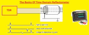
- The TDR measures the value of reflections over conductors. For measuring reflections, TDR releases an incident signal on the conductor and listens for this reflection.
- If the conductor has a uniform impedance value and is accurately terminated, then there are no reflections, and the remaining incident signal will be absorbed at the other end through termination.
- Then, if there are impedance changes, some incident signal will reflect to the source. The TDR has the same working principle as radar.
- The impedance of discontinuity can be measured through the amplitude of the reflected signal.
- The distance of reflecting impedance can be measured from the time that the pulse takes to return.
- The limitation of this process is that it has a lower system rise time. The total rise time comes with the combined rise time of the operating pulse and that of the oscilloscope or sampler that monitors the reflections.
What does TDR stand for?
It stands for Time-Domain Reflectometry. TDR is a technique used for testing the features of electrical lines by measuring reflected pulses.
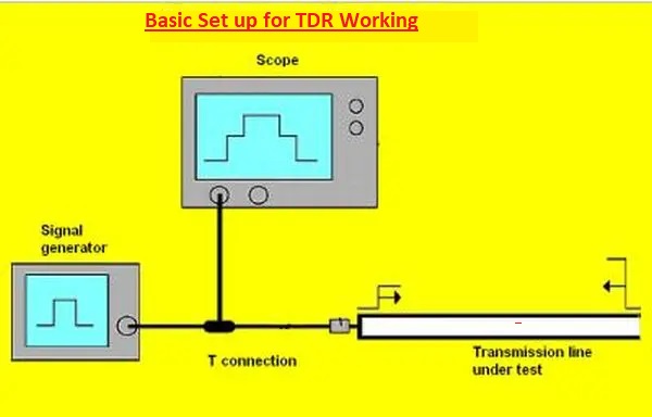
How does TDR work?
- The TDR is a test used for characterizing and finding faults in metallic cables. It transmits a short-rise pulse with a cable pair.
- If the cable pair comes with uniform admittance and is accurately terminated, the complete transmitted pulse will be absorbed at the distant point, and no signal will be reflected to TDR.
- The impedance discontinuities will result in some of the incident signals going back to the source. It is like the working of radar.
- The impedance increases, producing a reflection that reinforces the original pulse. The reduction in impedance causes reflection that affects the original pulse.
- This reflected pulse is measured at the output input to TDR and is shown or plotted as a function of time, and since the speed of the signal moving is constant on the cable pair, the net time of the pulse down and back is read as a function of cable length.
- Due to this sensitivity to impedance changes, the TDR is used to identify cable impedance mismatch features, like open cable pairs, shorted cable pairs, splices, load coils with smart coils, capacitance made in sections of cable, and the starting of bridged taps.
- The average impedance of a telephone cable pair is about 100 ohms. With TDR made for telephone cables, the baseline is 100 ohms. Some TDR shows the impedance through matching display lines to the reference on-screen.
Using the TDR
- When connecting TDR with the cable pair accurately terminated at the distant end, there can be an input or launch pulse on the left of the screen, and then the flat line will show to the termination.
- Any result on screen that is not baseline is an impedance mismatch like a launch pulse. The launch pulse is where clips are connected with a cable pair.
- The open cable pair has a higher impedance than the cable pair trace.
- The short or ground has less impedance than the pair, so traces are down.
- The splice has a small energy back and normally looks like an S on its side.
- The load coils help some energy to be absorbed; the face of the trace is not as sharp as open, and the back of the trace is longer.
- The lateral or bridged tap comes with less impedance at the start, and if the end of the bridged tap is open, part of the trace will be up. If the end of the cable is open, its trace will also be up.
- Series resistance shows back less energy, and due to its impedance, it is larger than the table cable pair and has enough gain used on TDR and will like the open cable pair.
Types of TDR
- TDR comes in analog and digital types. Digital TDR comes with a display on an on-screen LCD, and analog TDR has a signal on the RT screen.
- Analog TDR is commonly used in different applications, but digital TDR has some errors and can be easily used.
Time Domain Reflectometry
- A time domain reflectometer is used for semiconductor failure analysis as a non-destructive technique for the location of errors in semiconductor device packages.
- The TDR offers the electrical signature of single conductive traces in device packages and is best for finding the location of opens and shorts.
Applications of TDR
- TDR is commonly used for measuring the impedance of transmission lines, the dielectric constant of the medium of transmission, electrical conductivity, and its type, along with the position of faults in transmission lines.
- The main objective of this discussion is to find the level of water in the septic tank by placing TDR at the top of the tank.
Limitations of TDR
- The TDR technique comes with a relatively high instrument expense, potential limited applicability in high saline conditions due to signal attenuation, and the fact that soil-specific calibration can be needed for soils having larger bound water or high organic matter contents.
TDR vs. OTDR
- The basic difference between TDR and OTDR is the type of cable used for these processes. TDR is used for copper cables, and OTDR is made for fiber optic cables.
- TDR is operated by sending a pulse of electrical energy to the cable and measuring the time taken for the reflected signal to return.
- It is used for testing and finding faults in copper cables, like breaks, shorts, or impedance mismatches. TDR provides data about the distance to the fault and the magnitude of reflection, helping technicians pinpoint accurate points of issue.
- OTDR is used for testing and troubleshooting fiber optic cables. It operates by sending a pulse of light down the cable and measuring the reflected signal and the backscattered signal. OTDR can analyze the losses, attenuation, and reflectance features of fiber and also identify any faults or anomalies over cable length. That data is used for checking the quality of the fiber optic link and finding any breaks, bends, and splices that can be due to signal degradation.
- TDR has been used in the telecommunications and networking industry for a longer time, but OTDR has become common with the increasing adoption of fiber optic technology. Fiber optic cable has high bandwidth, longer distance, and immunity to electromagnetic interference, making it best for high-speed data transmission.
- OTDR has checked on the operation of cables to make sure of their reliability and minimize downtime.
- In some words, TDR is used for copper cables, and OTDR is used for fiber optic cables.
- But TDR has features for troubleshooting copper cables, and OTDR is becoming common for the maintenance and testing of fiber optic networks.
Read also
- What is a 10k Resistor? Explain 10k Ohm Resistor Color Code
- The Advantages of BA-EXT Weather Resistant Doors
- l1154f vs LR44: Top Picks for LR44 Battery Equivalents
- Introduction to Sensors and Transducers
- What Does an Anemometer Measure, Types & Work Process
- Types of Diode and Applications
FAQs
What is a time domain reflectometer (TDR) used for?
- Time domain reflectometers can be used for testing long cable runs and finding the breaks in cables, reducing the size and frequency of expensive cable repairs and reducing undesired span replacements.
What does a time domain reflectometer measure?
- A time domain reflectometer is a testing device that produces an energy pulse or step on a cable for finding the location and magnitude of cable faults, breaks, terminations, or other events along the length of a conductive cable.
What is a TDR, and what is it used for?
- It is a remote sensing electrical instrument technique that has been used for many years for finding spatial location and object nature. The early type of TDR from the 1930s that is commonly known is radar.
What is an example of a TDR?
- Simple TDR measuring of cable length with a broadband oscilloscope shows the TDR trace of a 15-foot-long cable with a delta t of 47.8 ns between the signal of the starting step and the reflected signal used for measuring cable length.
What is the reason for TDR?
- The reasons for using a TDR are
- To find breaks or faults in cables
- Measure the length of the cables
- To test the quality of cables
- The impedance of cables
Is TDR necessary?
- TDR is used for fault detection of electric wires in buildings, aircraft, and transportation systems; with that, TDR is used to find bad splices in phone cables and features of electronic devices and antennae.
How accurate is a TDR?
- Its main feature is to find the permittivity of material from wave propagation due to the strong relation between the permittivity of material and water content.
Is TDR used on live cables?
- This method is used to find defects, normally in electrical wires, by checking reflected spread-spectrum signals. This can be used in various high-noise and live environments.
How much time does it take to become proficient with a TDR?
- With the proper instruction, using a TDR is simple and can be learned in a few hours.
Is TDR expensive?
- A TDR ranges in price based on the type and manufacturer, but some tools are reasonably priced.
Is TDR used to locate faults in fiber optic installations?
- It analyzes the reflected signal, can find the distance to the fault, and offers data about impedance features and the integrity of the cable.
What are the basics of time domain reflectometry?
- The TDR works on the principle of radar. The pulse of energy is transmitted down a cable. When that pulse reaches the end of the cable or a fault along the cable, some part of the pulse energy is reflected back to the source.
What is the principle of the TDR test?
- The TDR sends a low-voltage pulse in the cable under testing, and at any impedance variation in the cable, the reflection will be checked. The TDR measures the time between releases and returns of low-voltage pulses from any reflections.