Hello friends, I hope all of you are having fun in your life. In today’s tutorial, we are going to have a look at synchronous motor starting methods. The running speed of the synchronous motor is equal to the speed of the field rotating at the stator, which is called synchronous speed. This speed depends on the frequency of input supply and the number of poles of the motor. The formula for synchronous speed is Ns = (120f/P), where f is the frequency and P is the number of poles of the motor. From this equation, we can conclude that the speed of a motor can be varied by varying the frequency of input and poles of the motor.
There are numerous benefits of synchronous motors due to the fact that they are mostly used in industries, like for power factor improvement. But it also has a main drawback: it is not a self-starting motor like the induction motors. In an induction motor, we just supply power to the stator, and it starts its operation, while in a synchronous motor, we need another extra supply at the rotor for excitation of the motor. The flux at the stator is revolving but at the rotor, due to the DC source connection, the flux is constant. In today’s post, we will have a look at different starting techniques and their practical implementation. So let’s get started with the synchronous motor starting method.
Synchronous Motor Starting Methods
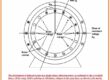
- For a practical understanding of the issue that occurs in the starting of motor we discuss the figure given below.
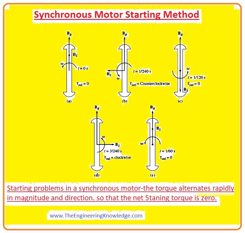
In this picture, the structure of a sixty-hertz synchronous motor at starting conditions, when input supply is provided to the motor is shown.
The rotor of the motor is static, so the field at the rotor BR is also static. The stator’s field BS starts to revolve in the stator at synchronous speed.
In the above figure, the circuit denoted as “a” tells about the motor at t=0 seconds, when the rotor’s fields BR and Bs are in a straight line. As we know, the torque-induced equation.
Tind = KBR x BS.
So the torque induced in the motor at t=0, according to the torque equation, will be zero.
The circuit denoted as “b” explains the condition when the time is t = 1/240 s. In this minor time interval, the motor hardly rotates; nonetheless, the direction of the stator’s field is towards the left side. According to the torque equation, the direction of torque on the rotor is anticlockwise.
The circuit in the above figure denoted as “c” describes the condition at (t=1/120s). At this time, the rotor’s field and the stator’s field are opposite to each other.
The circuit denoted by d explains the situation at t=3/240; now both the field of the rotor and the stator are ninety degrees to each other, and the torque direction is clockwise.
The last circuit that is denoted as “e” explains the situation at t = 1/60 s. At this time interval, both the fields of the stator and rotor are in a straight line.
You can observe from the above discussion that after completion of one electric rotation (cycle), first the torque direction was anticlockwise, then clockwise, and after completion of the cycle, the average torque was 0.
Due to such conditions, the motor starts vibrating after every electrical rotation (cycle) and gets overheated.
So there are 3 methods by which a motor can be operated safely.
Decrease the speed of rotation of the field to a point at which the rotor can easily interlock with it after half a rotation (half a cycle of the field. It is possible if we decrease the frequency of the input supply-connected motors.
The second option is to rotate the rotor with the external prime mover to the synchronous speed so it can interlock with the stator field; after that, remove the external prime mover, and the motor continues its operation.
The third possibility for motor starting is that it uses damper windings, also called amortisseur windings; we will explain the effect of this winding in detail.
Now we discuss these three factors for the starting of a synchronous motor in detail.
Synchronous Motor Starting by Reducing Electrical Frequency
If the rotation speed of the field at the stator is lower, the rotor can be very easily interlocked with it.
After that, speed can again reach its normal operating frequency, which is fifty or sixty hertz.
Rectifier inverters and cycloconverters can be used for this process, first to decrease frequency and then increase it.
With the invention of this circuitry nowadays, it is very easy to vary the frequency from zero to the desired value or overrated frequency.
If we link these frequency variable circuits with motor starting circuitry, then it is very easy to change frequency at the start of the motor and then increase it according to system requirements.
If the motor is working at a speed less than the rated, its internally generated voltage will also be less than the normal value of voltage.
With the decrement in internal generated voltage value, there will also be a decrease in terminal voltage of motor to maintain stator current at a safer level.
In any variable frequency starting circuitry, voltage will vary directly proportionally to the frequency variations.
Synchronous Motor Starting with an External Prime Mover
The second technique is to connect an external starting motor with a synchronous motor to get its desired rated speed.
When the motor gets its required speed, then remove the exterior motor connected to the synchronous motor.
When an external source is connected with the motor removed, then the speed of rotation of the shaft decreases; then the field of rotor BR lags the net field of a machine, then the generator behavior of the motor ends, and it starts to operate as a normal motor.
After that, the load can be connected with the synchronous motor for normal operation.
This entire process is not as absurd as it looks, as numerous synchronous motors are fragments of motor-generator sets, and the synchronous machine in the motor-generator set can start its operation with the other machine working as the starting motor.
Similarly, the starting motor is required to decrease the inertia of the synchronous machine without a load; the load connects with the motor until it is paralleled to the system.
As the starting motor is used only to decrease inertia, its power rating should be less than the motor to start.
Synchronous Motor Starting by Using Amortisseur or Damper Windings
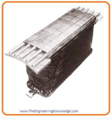
The most famous technique for starting a synchronous motor is to use an amortisseur winding; it also is known as a damper.
A pole face with a set of damper windings is shown in the given figure.
- For understanding in a given figure, the salient pole rotor with having 2 poles consists of damper windings is shown.
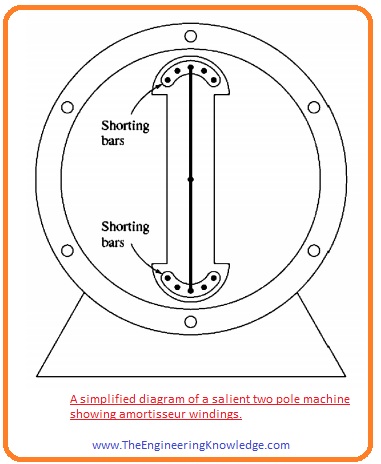
- This rotor displays damper winding with the shorted bars at the end points of the 2 rotor pole faces coupled by wires. (it is not the practical method to construction of a motor but it will help to demonstrate the point of the damper windings).
- Let us suppose that at start the field winding of the rotor is not connected with rotor and 3 phase input supply is provided at the stator.
- When the input supply is connected with the motor at (t=0s) suppose that field of stator Bs is at 90o it shown in the given figure.
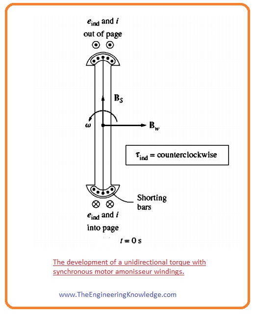
- As the stator field Bs rotates in an anticlockwise direction, due to its rotation, a voltage is induced in damper (amortisseur) windings is given as.
eind = (v x B).l
- In this equation, the ‘V’ is the rotation speed of bars relative to field.
- ‘B’ is the flux density.
- ‘l’ is the length of conductive material in the field.
- So the bars at the top of rotor are rotating at 900 to field, so the resultant direction of the voltage generated is out of the page. Correspondingly, the voltage generated is into the page at base (bottom) of the rotor bar.
- Due to these two generated voltages, the voltage-current produces at top bars out of page and at the bottom bars into the page, due to the winding field direction to the right side.
- According to the induced-torque equation, the resultant torque on the bars (and the rotor) is anticlockwise.
tind =kBw x Bs
- The given figure explains the conditions at (t =1/240s), in this situation the field of root has moved to ninety degrees but the rotor is almost at previous state, a rotor can’t move in this short time interval.
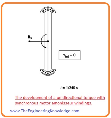
- In this situation, the voltage produced in the damper windings is 0, as the ‘V’ is parallel to field.
- Due to zero voltage production, there are no current windings and also torque will be zero.
- The given figure explains the condition at (t=1/120s), in this situation field of stator again has moved at ninety degrees but the rotor is still static.
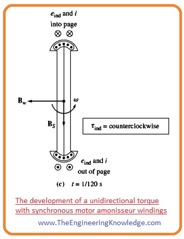
- The voltage produces in this condition in the damper windings is out of page at base (bottom) of bars and into page at the top of bars.
- The resultant current starts to flow at the bottom bars out of page and into a page at the upper (top) bars, due to this field Bw is in the left side.
- The resultant torque for this situation is anti-clockwise and given as.
tind= kBw x Bs
- the given below figure explains the condition at (t=3/240s), at this time interval the induced torque is 0.
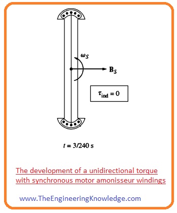
One thing you noticed is that at some points torque is clockwise, at some points it is anticlockwise and at some points it is 0, but it always rotates in one direction.
As the direction of net torque is unidirectional, there is an increment in the speed of the rotor.
It is completely different from starting a synchronous motor with its usual IF, as, in that case, torque is first clockwise and then anticlockwise, so average torque is 0.
But with damper windings, torques follow one direction, so it is not 0.
Though the rotor speed of rotation increases, it can never approach synchronous speed.
It is very simple to understand. Assume that a rotor is rotating at synchronous speed. So the speed of rotation of the rotor will be equal to rotor rotation speed, so there is no comparative (relative) speed between the stator field Bs and rotor rotation.
Due to the absence of relative motion, there will be zero torque induced in the windings. The resultant current will also be 0, and the field of windings will also be 0.
So there will be zero torque on the rotor to rotate it.
A rotor speed cannot equal synchronous speed, but it can be close to it.
It can be close enough to synchronous speed that the steady IF can be turned on, and the rotor will be aligned with the field of the stator.
In a practical motor, the field windings are not open when the motor is initiated. If these winnings are open, then the high value of voltage will be generated in them during the motor-starting process of the motor.
If these (field windings) are short-circuited at the starting of the motor, no hazardous voltages are created, and the induced IF essentially delivers additional starting torque to the motor.
Summary of Damper winding
- We can summarize the presence of damper windings in the synchronous motor as.
- Remove the field windings from direct current sources and make a short circuit of these windings.
- Then connect 3- phase source to stator, allow the rotor to reaches the synchronous speed. There should no load connected with a motor so it can easily get the synchronous speed.
- After that connect rotor field circuitry with the direct current source, then the motor will be interlocked with synchronous speed now you can connect load with the motor’s shaft.
- I also have written some related articles you can also read them are listed here.I
- Introduction to Synchronous Motor
- Synchronous Motor Torque-Speed Characteristic Curve
- Synchronous Motor Starting Method
- What is Synchronous Condenser (Capacitor)
- Synchronous Motor Power Correction.
- Types of Synchronous Motor
- Effect of Field Current Changes on a Synchronous Motor.
- Friends it the detailed and complete post on Synchronous Motor Starting Methods I have mentioned each and everything related to synchronous motor starting methods. If you have any query and questions about these methods can ask in comments. Thanks for reading. See you in the next tutorial.