 Hello, fellows, I hope all of you are having fun in your life. In today’s tutorial, we will have a look at the Starting Method of Induction Motors. A three-phase induction motor is hypothetically self-starting. The stating part of an induction motor comprises three-phase windings, when these windings connect with the three-phase supply generates a revolving magnetic field (B). This field will connect and cut the rotor conductors which will cause to produce the field in the rotor.
The field generated by the rotor will interrelate with the revolving field (B) in the stator and cause to rotate the rotor. So, three-phase induction motors employ a starting technique not to deliver a starting torque at the rotor, but due to these two reasons first one is to decrease heavy initial currents and stop the motor from over-heating and second is to Deliver over-load and no-voltage fortification (protection). In today’s post, we will see the different starting methods and their circuitry. So, let’s get started with the Starting Method of Induction Motors.
Starting Method of Induction Motors
- The induction motor does not show the starting issues which are present in the synchronous motor.
- In numerous situations, induction motors can be initiated by just linking them to the input supply.
- Though, there are occasionally due to some causes it does not possible. For instance, the initial (starting) current need can cause such a decrease in the power system voltage which across-the-line starting is not suitable.
- In the case of wound rotor induction motor starting conditions can be obtained at less current by adding an additional resistor in the circuitry of the rotor.
- This additional resistor not only enhances the starting torque also decreases the starting (initial) current.
- In cage rotor induction motors, the starting (initial) current can fluctuate extensively depending mainly on the rated power of the motor and on the effective rotor resistance at initial (starting) situations.
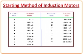
- To know the rotor current at starting (initial) situations, all cage motors now have a starting code letter on their name plates. The code letter puts restrictions on the quantity of current the motor can get during starting (initial) circumstances.
- These restrictions are stated in terms of the initial apparent power of the motor as a function of its horsepower ratings.
- In given diagram table is shown which covers the starting kilo-volt-amperes per horse-power for each code letter.
- To regulate the initial current for an induction motor, note the rated voltage, horse-power, and code letter from its name-plate.
- Then the starting apparent power of the motor can be found by the given formula.
Sstart = (rated horsepower) (code letter)
- The starting current can be found by this equation.
IL= Sstart/√3VT
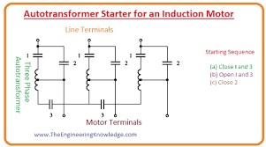
Auto-transformer Starter for an Induction Motor
- If essential, the starting (initial) current of an induction motor can be decreased by a starting circuitry. But, if it happens, it will also decrease the starting torque of the motor.
- One method to decrease the initial current is to add additional inductors or resistances into the power line during the initial (starting) condition.
- Although formerly common, this method is infrequent nowadays.
- A substitute method is to decrease the terminal voltage of the motor during starting by using an auto-transformers to step down these starting voltages.
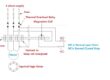
- The given diagram shows the typically decreased voltage starting circuitry using an auto-transformer.
- During initial conditions, contacts (1) and (3) are closed, providing a less voltage to the motor.
- When the motor is almost up to speed, contact one and three are opened and contacts (2) are closed.
- These contacts (connections) provide full-line voltage to the motor.
- It is significant to understand that while the initial current is decreased in direct proportionate to the reduction in terminal voltage, the starting torque declines as the square of the supplied voltage.
- So, only a particular quantity of current lessening can be done if the motor is to start with a shaft load connected
Induction Motor Starting Circuits
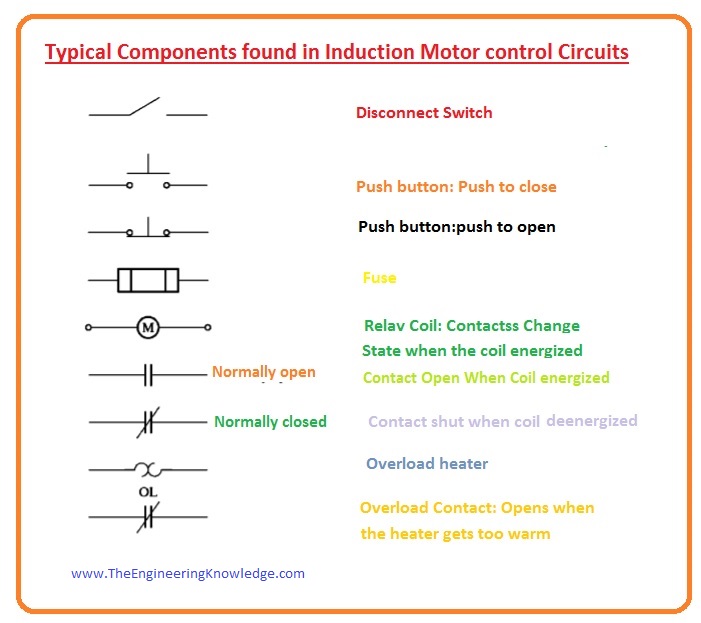
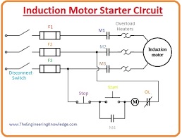
- A distinctive full-voltage induction motor starter circuitry is drawn is given a diagram.
- The components of this circuit is explained in this figure.
- The working of this circuitry is very simplest. When the start button is pushed, the relay (or contactor) coil (M) is energized, which causes the generally open contacts (M1, M2, and M3) to close.
- When these contacts closed, power is supplied to the induction motor, and the motor start working.
- Contact (M4) also closes, which shortens out the starting switch, letting the worker release it without eliminating power from the (M) relay.
- When the stop button is pushed, the (M) relay is de-energized, and the (M) contacts open, discontinuing the motor working.
- A magnetic motor starter circuitry has numerous protecting topographies which are mention here.
- Under-voltage protection
- Overload protection
- Short-circuit protection
Short-circuit protection
- Short-circuit safety for the motor is providing by fuses (F1), (F2), and (F3). If an abrupt short-circuit exits within the motor and origins a current movement several times higher than the rated value of current, these fuses will work, separating the motor from the input supply source and prevent it from burning and serious damage.
- Though these fuses should not damage during normal motor initial conditions, so they are intended to need currents numerous times higher than the full-load current before they open the circuitry.
- It clearly explains that if a short circuit happens due to high load at motor then these fuses will not be enough for this fault and cant clear this fault.
Overload protection
- Over-load protection to the motor is given by the component which is denoted in the diagram as (OL).
- These over-load (OL) protection components comprise of 2 portions, an overload heating component and over-load connections.
- Though this harm takes time, and an induction motor will not usually be damaged by short-term phases of high currents (like starting current).
- If the higher current is continued, then damage will happen. The over-load (OL) heating components also depend on the heat for their process, so they will not be get disturbed by short phases of higher current during the initial condition, and still, they work during the long time interval of higher current, eliminating power from the motor before it can be hurt.
Under-voltage protection
- Under-voltage protection to the motor is given by the controller circuit also. You can see from the figure that the controlling power for the (M) relay is coming from over the lines to the motor.
- If the voltage supplied to the motor becomes less, the voltage provided to the relay (M) will also decrease and the relay will stop to work or get de-energize.
- The (M) connection will be open and eliminating power from the motor terminals.
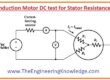
Three-Step Resistive Stator for an Induction Motor
- The starting circuitry of an induction motor with the resistances to eliminate the initial current of the motor is drawn in the given diagram.

- This circuitry is like the former circuitry which we have discussed, excepting that this circuitry has some extra elements which govern the elimination of the starting resistance.
- In this circuitry you can see that the relays which are denoted by (1TD, 2TD, 3TD), all these relays are time delay relays, they called time delay because when these relays get energized they will take some time which is set on these relays to close their contacts.
- In this circuit when the starting button is pressed then relay (M) gets energized then the supply will provide to the motor. the complete starting resistance is in series connection with the motor, which lessening the initial current.
- When the contact (M) gets closed, you can see that the 1TD relay is energized. Though, there is a limited delay before the 1TD contacts get close.
- Through this time delay, the motor partly speeds up, and the initial current drops to some extent.
- After this time interval contacts of 1TD get closed and eliminating out a portion of the initial resistor and instantaneously energizing the (2TD) relay.
- After some time, interval contacts of 2TD relay get closed, and it eliminates the 2nd portion of resistance and it energizes the (3TD) relay.
- In the end, the (3TD) contacts get closed, and the complete starting resistance is out of the circuitry.
- By a sensible choice of resistances values and delay of time, this initial circuitry can be used to stop the motor starting current from becoming hazardously large, while still letting sufficient current movement to confirm rapid acceleration to ordinary operation speeds.
It is the completer tutorial on the starting method of an induction motor if you have any query ask in the comments thanks for reading. See you in the next tutorial.
You can also read some related articles to the induction motor. That is described here.
- Introduction to Induction Motor
- Introduction to Three Phase Induction Motor
- Equivalent Circuit Induction Motor
- Induction Motor Torque-Speed Characteristics
- Variations in Induction Motor Torque-Speed Characteristics
- Power and Torque in Induction Motors
- Induction Motor Design Classes
- Induction Motor Design