Different rigid-flex PCB-based projects easily pass engineering validation tests and design validation tests but still face failures during bulk production or after months of field operation. That gap between prototype and reliability for longer duration is an engineering challenge for rigid-flex design, which is why experienced rigid-flex PCB manufacturers place a strong focus on reliability from the earliest design stage.
Normally, failure modes come for cracking of the flexible part, delamination between the rigid and flexible component, and improper electrical connection through a bad structural transition. For different conditions, these failures do not occur through a single design error. But they come from collective effects of material used, mechanical stress stackup imbalance, and manufacturing process limitations.
So rigid flex board, no layout errors. It is multidisciplinary engineering challenges that come with mechanical behavior, material science, manufacturing constraints, and planning for long-term reliability.
A design that seems accurate electrically cannot mechanically work if these parameters are not considered. Understanding of failure mechanisms at early phases is important for designing rigid-flex boards that perform reliably in manufacturing and also for real-world applications.
What is a Rigid-Flex PCB
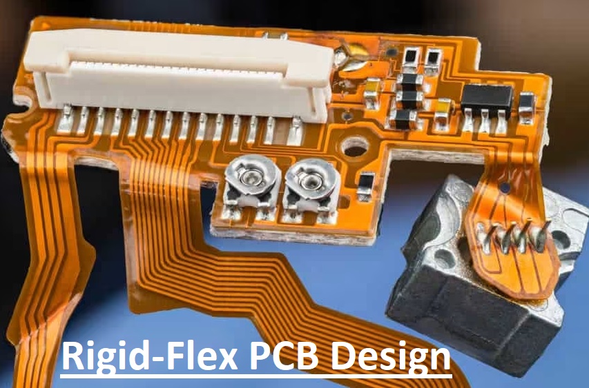
A rigid-flex board is defined as a circuit board that is made with a combination of rigid and flexible parts, but this definition is limited from an engineering perspective.
A rigid area used for offering structural support and working as a mounting structure where electronic components like connectors, ICs, sensors, and power devices are connected. It works like a conventional FR4 board that offers dimensional stability with mechanical strength.
Flexible area performs different functions like interconnection systems and also absorbs mechanical pressure that occurs with vibration, movement, thermal expansion, or assembly parameters.
In place of employing connectors, a flexible part is helpful for the electrical connection movement with the product. So a rigid, flexible board is inspected as a mechanical, electrical hybrid system compared to a circuit board. The rigid part supports electronics, and the flex part manages mechanical strain and enhances reliability.
If anyone does not have a proper understanding of this condition, it causes design failure. If a flexible part is used as a routing space, then the stress management structure causes high chances of long-term failure.
Failure Factor: Mechanical Stress & Bend Design
Mechanical stress is the main cause of rigid flex PCB failure, mostly in products that face bending forces, vibration, assembly movement, and thermal cycling.
Bend Radius Rules
Bend radius helps to find out how much strain copper faces during flexing.
General engineering rules:
- Static bending: ≥ 6× total flex thickness
- Dynamic bending: ≥ 10–15× total flex thickness
Static bending refers to installation bending that occurs once or occasionally. Dynamic bending is repeated movement at the time of product operation, like foldable electronics or moving medical devices. If the bending radius is small, stress will rise sharply. The result of copper fatigue is followed by cracking, crack growth, and, in the last, open-circuit failure.
The failure sequence is usually:
Stress concentration → Copper fatigue → Micro-crack formation → Crack propagation → Electrical failure
designers sometime underestimates it since failure cannot be inspected instantly during testing.
Bookbinder Effect
For multilayer flex circuits, internal and external layers do not face the same strain when bending occurs. External layers face high stretches, and internal layers compress differently.
This non-uniform strain distribution is known as the Bookbinder Effect.
It causes interlayer stress imbalance, which increases copper cracking chances, adhesive damage, and layer separation.
Engineering solutions are
- symmetric construction
- reducing flex layer count where possible,
- minimizing unnecessary conductor layers in bend regions
The fewer layers involved in bending, the lower the chances of mechanical risk.
Neutral Axis
The neutral axis is a point in a flexural structure where mechanical strain is least during bending. Closeness to the copper conductor to the neutral axis reduces stress. That is an important rule for rigid-flex design. If copper is put at a distance from the neutral axis, bending stress is high and reduces reliability.
A proper stack-up design helps to position important conductors close to the neutral axis.
Flex Area Routing Rules
Flex routing should be according to mechanical rules, not only electrical rules. Failures started since the routing decision ignored bending features.
Route Traces Perpendicular to the Bend Direction
Traces should be routed at 90 degrees to bending. That helps strain to distribute smoothly over the conductor. parallel routing over a bend line increases the chances of stress concentration and crack propagation.
Avoid Sharp Corners
A sharp 90-degree corner causes local stress concentration points. that become crack initiation sites for repeated flexing
Use:
- curved routing
- teardrop transitions
- smooth radius corners
This minimizes local mechanical stress and enhances fatigue life.
No Vias in the Bending Area
Vias are rigid structural discontinuities and are never put in the active bending area.
They create:
- localized stiffness changes
- stress concentration
- placing crack risks
Vias should exist outside the bending area whenever possible.
Keep Copper Distribution Balanced
Nonuniform copper distribution resulting in asymmetric mechanical features during bending and thermal cycling.
Balanced copper helps reduce:
- warpage
- twisting
- delamination
- stress concentration
This is an important DFM rule often overlooked during layout optimization.
Materials: Why RA Copper Is important
The material used defines either rigid flex board work longer.
Base Material SystemThe
rigid part is made with FR4 since it offers
- mechanical rigidity
- good thermal stability
- reliable component mounting
Flexible part made of polyimide (PI), which provides
- good flexibility
- high temperature resistance
- strong dimensional stability under repeated bending
These two material transitions are needed to make it properly.
RA Copper vs. ED Copper
Copper is important since it offers reliability.
Rolled Annealed (RA) Copper
RA copper offers
- Ductile strength
- higher fatigue resistance
- good bending performance
Its grain structure is elongated and uniform, offering to tolerate repeated mechanical strain without cracking.
Electrodeposited (ED) Copper
Red copper has high chances for failure in flex projects. It has a high columnar grain structure that provides a natural fracture path for repeated bending stress. that make copper cracking have high chances normally in dynamic flex designs.
For static flex, ED copper is sometimes used; in dynamic bending, RA copper is normally an engineering requirement.
Adhesiveless Laminates
Adhesiveless laminates provide more reliable features than adhesive-based constructions.
The main advantages are
- thin overall design
- Good dimensional stability
- less delamination risk
There is no separate adhesive layer working as a weak interface; reliability increases in heat and repeated bending. For highly reliable features, adhesiveless polyimides are used.
Stack-up Design: Where Most Problems Start
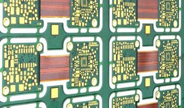
Rigid-flex reliability errors started in the stackup design, much longer before starting routing.
Symmetric vs. Asymmetric Stack-up
Symmetric stackups provide balanced stress distribution at times of bending and thermal cycling.
An asymmetric stack-up provides
- uneven strain distribution
- warpage
- high delamination risk
- unstable long-term reliability
Symmetry is important in multilayer flex parts.
Neutral Axis in Stack-up Design
Stack up the design control natural axis location. The main work is
Important copper layers should be configured close to the neutral axis since it reduces bending strain and provides high fatigue resistance.
Common Design Mistakes
The main engineering errors are
- Put the copper at a larger distance from the neutral axis
- Use of excessive flex layer count
- designing an unnecessary multilayer flex part
- Poor rigid-to-flex transition planning
7. Manufacturing Constraints You Must Consider
A design that is not made properly with high reliability is not a good design. Starting coordination with a rigid flex pcb manufacturer is important.
Laser Drilling and Microvias
A fine-pitch rigid flex design is needed. Laser-drilled microvias for density interconnections
However, microvias increase
- process sensitivity
- registration demand
- plating reliability chances
They should be used only where needed.
Controlled Depth Routing
Controlled depth routing is used accurately for defining rigid and flexible transitions
Bad depth control can cause the following:
- mechanical weakness
- exposed copper damage
- uniform stress concentration
Precision here directly affects the product’s working life.
Multi-Lamination
A rigid flex board needs different lamination cycles since rigid and flex materials should be connected.
Repeated lamination increases:
- alignment error
- delamination probability
- manufacturing complexity
- production cost
Each extra lamination cycle minimizes process margin.
Proper Flex Release
The flex area should be accurately released at the time of manufacturing so it moves as designed without residual stress.
Improper release of the result of
- trapped internal stress
- unexpected cracking during assembly
- Bad long-term bending reliability
Manufacturing planning should start during design, not after Gerber release.
Reliability Risks & Failure Mechanisms
Rigid-flex failures are usually progressive, not sudden.
Copper Fatigue Cracking
Repeated bending causes cyclic strain in copper conductors.
Over time:
micro-strain → fatigue damage → crack initiation → conductor fracture
It is a common failure mechanism for dynamic flex applications.
Delamination
Delamination occurs when bonding between layers weakens in result of
- poor material compatibility
- thermal cycling
- high mechanical stress
- weak adhesive interfaces
This occurs after long-term field use rather than during early testing.
Thermal Stress from CTE Mismatch
Different materials have different
FR4, polyimide, copper, and adhesive systems all come with different CTE values.
This causes
thermal cycling → interfacial stress → fatigue accumulation → long-term reliability degradation
CTE mismatch is important for the vehicle and aviation industries, where temperature cycling is high.
IPC rigid flex design details give importance to these risks, specifically, liability based on mechanical and thermal strain management.
Application
Rigid-flex PCBs are used where electrical and mechanical factors are involved together.
Aerospace
Aerospace systems needed
- vibration resistance
- less weight
- high reliability under thermal extremes
Rigid-flex reduces the use of connectors, and wire harness reduces damaging points by making the system robust.
Medical Devices
Medical devices often use
- miniaturization
- repeated movement
- long-term reliability
Common examples are portable imaging systems, implantable devices, and surgical devices where connector damage is unacceptable.
Automotive Electronics
Some applications, like BMS and ADAS, needed
- vibration tolerance
- thermal cycling resistance
- compact packaging
Rigid-flex enhances reliability for harsh conditions where conventional cable connections do not work.
Consumer Electronics
Foldable devices and wearables are needed
- high space optimization
- repeated movement
- less-weight construction
Rigid-flex is important since connectors enhance size, weight, and chances of failure.
The decision is operated through engineering necessity, not convenience.
When NOT to Use Rigid-Flex PCB
Not every design uses rigid-flex.
It is often the wrong option used for the following:
- low-cost projects
- products without space requirements
- designs with no vibration or motion-related demand
- systems where connectors are already reliable
Rigid-flex introduces the following:
- High material cost
- Complex manufacturing
- longer qualification cycles
- high DFM requirements
If products do not feature stress relief, connector elimination, or space minimization, standard rigid boards with cable assembly are good engineering options.
The use of rigid flex without proper functionality enhances cost without improving reliability.
Cost Engineering & Optimization Strategy
Rigid-flex is a costly process, but smart engineering can minimize cost significantly.
Main Cost Drivers
The largest cost contributors are
- materials (polyimide and RA copper)
- process complexity
- yield challenges during manufacturing
Multi-layer flex parts are costly because they combine difficult materials with narrow process windows.
Optimization Strategies
Good cost optimization techniques are
- Reducing flex layer count
- Limit the bend area
- simple stack-up
- avoiding unnecessary microvias
- Reduced repeated lamination cycles
Total Cost of Ownership (TCO)
Although the initial fabrication cost is higher, rigid-flex can control net system cost by lowering the following:
- connector charges
- manual assembly cost
- field maintenance cost
- warranty failure cost
Fewer connectors often show fewer failure points and low service demand.
The accurate evaluation is based on TCO, not only PCB manufacturing cost.
12. Conclusion
Most rigid flex failures do not occur mistakenly. They occur from bad coordination between material mechanics, design, and manufacturing processes. Cracking of copper, delamination, and thermal fatigue started a longer time before field failure was shown. The main cause is an early engineering decision, improper bending radius, bad stackup symmetry, wrong copper used, or ineffective manufacturing planning.
So DFM is important; proper rigid flex development is needed for early use from design engineers, mechanical teams, process engineers, and manufacturing specialists.
A rigid flex board is not just a board design operation; it is a system-level engineering fault. When accurately designed, it offers main reliable features and performance features with reduced connector numbers, assembly complications, and longer service time.
Accurate design also improves long-term performance by reducing interconnection failures and simplifying assembly. This becomes effective when supported by strong turnkey PCB assembly planning from the beginning of the project, especially when working with trusted, advanced PCB fabrication experts who understand both design reliability and manufacturing precision. Their expertise in turnkey PCB assembly services also helps businesses simplify manufacturing with complete design, fabrication, and assembly under one roof. The best result occurs when reliability is followed from the first day and not checked later.