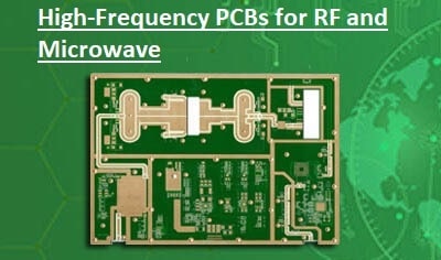
RF and microwave circuits are commonly used in PCB board design in industries famous for features to handle higher frequency as compared to normal circuits. RF and microwaves are the main parts of different commercial and professional uses like wireless communication devices in phones, and satellite broadcasters.
RF AND MICROWAVE PCB BASICS
The easy-to-define RF and Microwave baord is that comes with components that carry RG signals. These signals have different frequencies and these differences define RF and microwave boards and other types.
Handing the basics of RF and microwave frequencies is the first parameter for defining the RF PCB board design and microwave PCB design.
Electronic signals change with time and communicate details. The quantity changes is voltage or current. These signals are passed between devices for data transmission such as video, audio, etc.
Radiofrequency changes between 3 kHz and 300 kHz, but are divided in small types that are listed here
Low-Frequency Signals:
These are signals configured with conventional analog components and added signals with a frequency of about 50 MHz.
RF Signals:
RF signals cover different ranges of signal frequencies, and circuit designers use terms in a narrow scope. In this field, RF signal frequency is about 50 MHz to 1 GHz. The same signal frequencies are used for AM/FM transmission.
Microwave Signals:
Microwave signal has a frequency of more than 1 GHz. The upper limit of the signal is about 30 GHz. It is the same microwave used for cooking food in microwave ovens. It is also used for communicating high-bandwidth signals.
PCB DESIGN BASICS
RF and microwave baord must made to reduce errors at the time of the assembly process. Some basic RF layout desing are
Parts Separate:
If the board comes with different parts, such as low-level analog, RF, and digital components, keep them separate. Isolating high-frequency microwave components from low-speed digital lines is critical to preventing signal degradation. It is easy to design and reduces issues at the time of the assembly stage
Multilayer PCBs:
- RF and microwave boards come with more than one layer. Upper layers come with a power stage and RF signal lines and components. Make sure if multilayer board, there is a ground layer below any layer that comes with RF or microwave signal lines.
Sensitivity to Noise:
- Designers of these boards also know the sensitivity of high-frequency signals is noise. Some engineers working with this sensitivity for high-speed digital signals and be cautious about RF and microwave signals, as they are high sensitive. These signals are chances to produce different noises. This high sensitivity defines the chances of signal noise
Read also:
- Special Processes for Flexible PCB
- PCBWAY KiCad OPEN SOURCE DESIGN CONTEST
- PCB Heat Dissipation Techniques
- Learn How PCB Circuit Board Soldering Guide for Beginners
- PCB Prototype Manufacturing and Assembly
Faqs
- Traces that join RF components are as short as possible, enough spaced, and configured on adjacent layers if they are crossed with sensitive signals. For stack, the best method is a multilayer structure of 4 layers
- FR is a flame retardant and FR4 materials are commonly used and have low cost, PTFE is good for RF/microwave PCBs working at WiFi frequencies.
- RF board comes with low MHZ frequencies for high GHz. The materials used for the board are important for signal quality, proper working, and operation for high frequency. Dielectric contact is a factor in choosing PCB material
- Creating RF board desing needed proper working for handling different problems. Considering frequency consideration, component setting, EMI control, and manufacturing testing helps to make high-performance RF PCBs.
- Microwave boards are different as compared to standard boards based on the material used. Special material used for moving signal frequencies. normally materials that can be used are Arlon, GETEK, Teflon, and Rogers, based on request. If requried hybrid materials can used
- RF boards are controlled impedance lines and low-cost dielectric materials for painting signal quality at multi-gigahertz frequencies.
- The digital board uses standard FR4 and works on high-speed digital data transmission.
- ENIG is a common option and is used in about 80 percent of all boards, This finish offers thin, gold solderable features that protect copper traces with a nickel barrier. ENIG is the best lead-free option due to its durable and long-lasting features
- High-frequency board, either rigid or flexible provides faster signal flow rates and the frequency range is about 100 GHz.
- It is good that there are many materials made for operating for high-frequency levels