
 Hello, friends welcome to the new post. In this post, we will discuss the details about Transformer Protection and faults occurring in it. The transformer is such an electrical device that used to vary the voltage level from one to another or high to low or low to high according to the requirements of the system. The main parts of the transformer are core windings and insulation.
Due to the main component of the system, it needed a certain type of protection from the different faults occurring in the system. In this post we discuss details about the faults that occur in the transformer and how can minimize these faults. So let get started with Introducion to Transformer Protection
Introduction to Power Transformer Protection
- The configuration of the power transformer is such that there are numerous errors can exist in this device than other types of components used in the system like generators motors, etc.
- To provide protection to the transformer from errors there is different subcomponent are employed like a relay, pressure relay, breakers fuses, etc
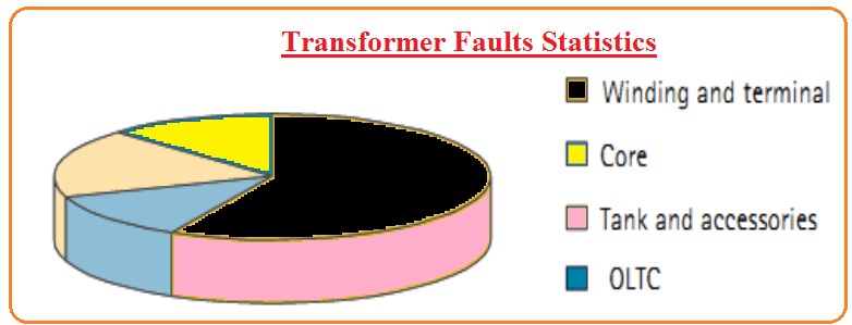
above the insulating oil. - In the below figure you can see the structure of the main faults that occur in the transformer.
- The main factors over which the protection of transformer relies are mentioned here with detail.
- Transformer Ratings
- Existing Position
- Transformer VOltage
- Desing
- Let us discuss these points with the detailed
Transformer Ratings
- In below table, the rating of the transformer and respective protection are mentioned.
-
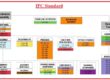
Transformer Rating Protection Devices 2500kVA Till this rating, there is the use of fuses or thermal overload relay 2500 to 5000kVA Fuses and overcurrent relay is employed 5000 to 10000kVA With fuse, overcurrent relay differential relay is employed Over10MVA For these ratings, there is use of fuses, over current relay percentage protection relay Transformer Location
- The 2nd point takes into consideration for transformer protection is the location of the transformer where it located.
- It the transformer is located or installed at the high-level system or generation side then it needed special protection and design configuration.
- But in the case of a distribution transformer there is just one differential relay and over current needed.
- It it is located near to the generation system so there will be a large value of inrush current flow so it needed a high value of restraint relay
Transformer Voltage and Desing
- There is a certain configuration is needed for large value of voltage handling through the transformer and high prices for faults removal.
- So the connection of windings is such that in a three-phase transformer there is Y or delta configuration is used.
- There is the usage of tertiary windings, tap changes, and different types of the ground system is employed.
Transformer OVercurrent Protection
- To provide overcurrent protection to transformer there is fuses time delay relays and instantaneous relays are employed.
Fuse
- The fault removal or operating capacity of the fuse is such that as a short circuit occurs it interrupt the system
- The value of the rating offered by the fuse should be high than the extreme load link to the transformer. Generally, fuse rating should be larger than one fifty percent of high load linked to it
- There should be no effect of transformer magnetization current at the fuse.
- The least melted features of the fuse should be supported to the other protection component employed at less voltage part of the device.
- The ratio among the least melted current for 2 differently parted values like 0.1 and one hundred seconds is called speed ratio. Its value should be large as possible.
Time Delay Relay
- To minimize the fault due to excessive overload there is the use of a time delay relay called overcurrent relay.
- The value of adjustment for this device should be one fifteen percent of the highest overload.
- The time delay overcurrent relay fulfills the fewer side voltage components. That consists of low voltage bus relay, transformer, and faults of breaker
What is Percentage Differential Protection
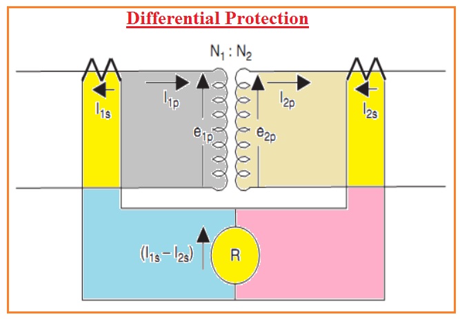
- In the case of a conventional power transformer, the equation of percentage differential protection is.
N1I1p=N2I2p
- If there is the usage of current transformer that are in the turns ratio of 1: n1 and 1 :n2 so current passing in the transformer will be,
- N1nI1s=N2n2I2s
- If we choose the current transformer then we can create N1n1 = N2n2 and for the general transformer, the current is i1s = i2s.
- Though if an inner fault created this situation will not be satisfied and there will be a larger difference between the I1s and I2s.
- In reality, its value is proportionate to the fault current
- The differential current offered the high sensitive calculation for fault current.
- Id=I1s-I2s
Problem in Differential Protection
- There are some issues that occur in the differential protection mentions here.
- Different CT Ratings
- Difference faults of Transformations
- Tap Changer of Transformer
- Let’s discuss
- It is very difficult to get such current transformer rates that fulfill both primary and secondary parts or this below-given equation.
- N1n1 =N2n2,
- It is due to the usage of different CTs values.
- To get the required results their usage of auxiliary current transformers.
- In this condition, there is no match between Cts and that caused less differential current id in normal circumstances.
- In some cases, there is an error that occurs in 2 current transformer that has different values and caused a larger value of differential current in case of fault.
- In the case of a tap changer in the transformer, there is will be a change in the ratio of the transformer in case of tap is changed at the tap changer
Percentage Differential Protection
- In percentage differential relay the differential current should not be large than the value of certain %age of current passing in the transformer.
- This current is called through current which is the average of primary and secondary current.
Ir=(I1s+I2s)/2
- the current ir is called restraint current is used to generate certain torque at moving coil
- the main features of percentage differential relay are discussed here

False Differential Currents Causes
- The main causes of differential false current are mentioned here.
- Magnetizing Inrush Current Energization
- Inrush Current Harmonic Components
- Magnetizing Inrush in Fault Removal
- Sympathetic Inrush
- Transformer Over-excitation
- CT Saturation
- Let us discuss the point with details
Magnetizing Inrush Current through Energization
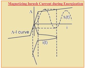
- Let us assume that power transformer in case of no loading state there is energization occurs. When the button is press voltage is given to the transformer and magnetizing current passes and voltage and flux due to voltage is given here.

- In practice, the magnetizing inductance of the transformer is not linear. If the flux value is larger than the saturation knee point then a high current will comes from the power supply.
- the value of this current is can be found through the slop of magnetization features in the saturation state.
- It is ceratin that magnetization inrush current of error current is ceratin
- it must be mentioned that in ceratin transformer the large inrush current exists according to the energization process and resonant flux in the device.
- This inrush current is passing at the primary side not at the other side and it is obvious that it makes differential current that is two hundred percent of the retraining current result the error.
Inrush Current Harmonic Components
- the error caused to the %age differential relay in a transformer is stopped through the use of inrush current occur in the harmonic elements.
- In case of error, the current is accurate fundamental frequency elements
Magnetizing Inrush in Fault Removal
- In case of exterior error, the transformer can be separated from the circuit through the use of a circuit breaker the state in the transformer core is like occur to the magnetization of the transformer.
- If the voltage given at the transformer windings is larger to the condition before fault to normal state after the fault occur then flux linking in the transformer core is after that vary from less pre error state to normal condition
- According to the time over which error is eliminated the transition can case dc offset at flux crossing and primary current signal like to the occurring in the energizing.
- In case when no residual flux in the transformer core the inrush in is less than through transformer energization
That is a detailed post about Power Transformer Faults and Protections if you have any query ask in the comments. Thanks for reading have a good day