 Hello fellows, I hope you are doing great. In today’s tutorial, we will have a look at Power Supply Troubleshooting & Repair. The power supply is electronic instruments used to provides electrical power to the load connected. Normally it transforms one category of electric energy into other forms of energy with that it also transformed other types of energies like mechanical, chemical, etc into electric power.
There are numerous types of power supplies according to their use and circuit such as AC power supply, DC power supply, AC to DC, regulators, etc. In today’s post, we will have a detailed look at how to troubleshoot any power supply and if some fault occurs in supply how to solve that fault. So let’s get started with Power Supply Troubleshooting & Repair.
Power Supply Troubleshooting & Repair
- Troubleshooting a type of logic thinking join with the detailed information of any electrical circuitry or operation any network to detect and resolve the error.
- For troubleshooting there are 3 steps are followed analysis, planning, and measuring.
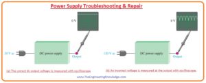
- For instance in the below figure denoted as (a) a correctly operative dc power supply is shown by a block with a known input signal and an accurate output voltage.
- While in figure denoted as (b) dc supply is denoted with the input and corrupted output.
Analysis:
- The ist step for troubleshooting of any faulty circuitry is to examine the issue which comprises finding the indication and removing as many reasons as possible.
- If we see in figure (b) shown above that output of dc supply is not proper dc voltage. This indication does not explain about the exact cause of this issue.
- In other conditions, though, a specific indication can point to a given area where an error is most likely.
- The ist point that you have to do for in examining the error is to attempt to remove any obvious reasons.
- In normal condition you ensure that the input terminal is connected with the power source and fuse is working properly.
- While for a system where the battery is providing power battery must be operating properly.
- With the checking of input power also uses your mind to find likely errors such as damage resistance, disconnect the wire, loose connecting wire, or burnt fuse.
- But be very careful during observing circuit it can cause any possible shock or burn.
- For irregular damage, the circuitry can work correctly for sometime and then damage due to heating.
- As a law, you should always do a sensory check as part of the analysis phase before proceeding.
Planning
-
- In this stage, you deliberate how you will solve the error. There are 3 probable methods to troubleshooting most circuits. First start from the input side in case of dc supply analyze from the secondary of a transformer from inputs voltage are coming and move to the output until you find and corrupted value.
- When you find zero value of voltage you have pointed the error to the portion of the circuitry among the last testing point where the voltage was fine and the present testing location.
- In all troubleshooting methods, you should identify what the voltage is assumed to be at every location in order to identify an improper calculation when you see it.
- In the second step initiate from the output terminal of circuitry and move towards the input. Find voltage at every point till you get an accurate value.
- At this point, you have separated the issue to the portion of the circuitry among the last testing location and the recent testing location where the voltage is accurate.
-
- In the third step use half splitting technique and initiate in the mid of the circuitry. If this calculation indicates a precise voltage, you recognize that the circuitry is functioning correctly from the input side to that testing location.
- It shows that errors are exits among the current testing location and output terminal, so initiate locating the voltage in the direction of output terminals.
- If the calculations at the midpoint of circuitry indicate zero voltage of error voltage, you can find that errors are exits between the input and testing point.
- So, initiate finding the voltage from the testing point to the input side.
- For a demonstration, let’s suppose that we apply the half-splitting method using an oscilloscope.
Measurement
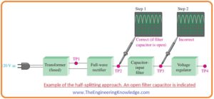
- In the below figure the half splitting technique is explained with the calculations representing a specific error in this condition the fault is the filter capacitor.
- In the figure, you can see that testing point TP2 providing the output of a full-wave rectifier which directs that both transformer and rectifier are working correctly.
- These calculations also describe that the filtering capacitor is an open circuit that confirmed at the TP3 full-wave voltage.
- If filter circuitry is operating correctly, you will find the value of DC voltage at TP2 and TP3 points.
- If the filtering capacitor is short-circuited you will have zero voltage at all testing points since the fuse has damaged.
- The short circuit at any point in the circuitry is very challenging to separate if circuitry has fuse then it will damage if a short circuit occurs at any point of circuitry.
- For the situation described in the above figure, the half-splitting technique acquired 2 calculations to separate the error to the open filter capacitor.
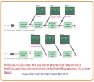
- If you had ongoing from the secondary side of the transformer, it has 2 and if you initiated from the final output, you also have 3 calculations as shown in the below figure.
Fault Analysis
- In some situations, after separating an errored portion to a specific circuitry, it can be compulsory to separate the issue to a single element in the circuitry.
- On this occasion, you have to use logical approaches and your information of the indications produced by special constituent damaging.
- Some distinctive constituent catastrophes and the indications they cause are explained below.
Effect of Open Diode in Half-Wave Rectifier
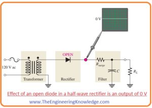
- In the below figure half-wave rectifier with the filter having open diode is shown below.
- The resultant indication is 0 output voltage as designated. This is clear since the open diode pauses the current route from the secondary side of the transformer to the filter and output resistance and so current is zero.
- Other errors that will origin a similar indication in this circuitry are an open circuit winding of a transformer, zero voltage at the input and open fuse.
Effect of Open Diode in Full-Wave Rectifier
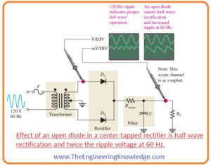
- In below figure the center-tapped rectifier circuit having a filter is shown.
- If any diode in the circuitry is open then there will be double the ripple voltage at a sixty-hertz frequency than the one twenty hertz frequency.
- Another error that will origin a similar indication is an open circuit secondary winding of a transformer.
- The cause for the augmented ripple voltage at sixty hertz than at one twenty hertz frequency is as follows.
- In the above circuit, if one diode is open-circuited there will be current across load resistance RL for half cycle of input.
- For the other half cycles of the input signal the there is no current due to open circuit diode for this cycle.
- The consequence is half-wave rectification, as shown in the above picture, which generates a higher ripple voltage with a frequency of sixty hertz.
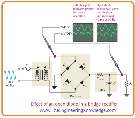
- The bridge full-wave rectifier is shown below in this circuitry open diode also generates a similar indicator as in the center-tapped circuitry, a bridge rectifier is shown below.
- The open diode stops current through load resistance for half cycle of an input signal.
- Due to this only half cycle is rectified that generates two times the ripple voltage at the sixty-hertz frequency that normally generated at one twenty hertz frequency.
Effects of Faulty Filter Capacitor
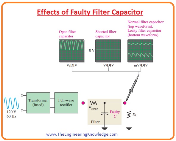
- Three types of errors of the filter capacitor are described here in the below figure.
- Open: If the filtering capacitor in full-wave rectifier circuitry is open than the output of circuitry will be full-wave rectified voltage.
- Shorted: If the filtering capacitor is short-circuited than there will be zero output. Due to the short capacitor, the fuse will be damaged.
- If a fuse is not correctly used then due to shorted capacitor all diodes in the circuitry will burn out due to the large value of current and output is zero.
- Leaky:
- The leaky filter capacitor is equaled to the capacitor having a parallel leakage resistor.
- The leakage resistor decreases the time constant RC and capacitor releases charge very fastly as normally do.
- That increases the ripple voltages at the output terminals of circuitry but these faules occur very rarely.
So friends that is complete post about Power Supply Troubleshooting & Repair if you have any query about this post ask in comments. See you in the next interesting post have a good day.


