 Hi, readers welcome to the new post. IN this post we will learn Introduction to PNP Transistor. Transistor is a device that is employed in different switching and amplification applications. It has 2 main categories first one is NPN and the second one is PNP. PNP transistor has such structure that there is three layers at both ends has material of P types and at mid N semiconductor is positioned.
There are three main terminals it has first one is the emitter second one is the collector and the third one is the base. Here we cover different parameters about these components and learn how can use them in different projects so let get started.
Introduction to PNP Transistor
- Today’s electronic circuits are based on silicon and since silicon based transistors can withstand a lot of voltage and a lot of currents, they are considered very good transistors.
- However, during the manufacturing process, silicon transistors sometimes suffer from swelling at certain points that cause them to deform. P-type and N-type semiconductors can be used in the creation of PNP transistors, since these two semiconductors can withstand a lot of voltage and a lot of current.
- In fact, a typical PNP transistor has a lifetime of thousands of hours and cannot melt under 7C.
- Also, a PNP transistor can withstand 100A, whereas the NPN transistor can only handle 7A.
- So why use PNP transistors in electronic circuits instead of the good old NPN transistor?
The working of a PNP transistor
- A typical PNP transistor is built with a donor and an acceptor semiconductor. The N-type semiconductor contains one positive and one negative type of electrons. On the other hand, P-type semiconductors contain holes or holes.
- So when the electrons pass through the PNP transistor, they can be collected as ‘on’ or ‘off’ values, whereas when they pass through the PNP transistor, they can be collected as ‘on’ or ‘off’ states.
- To construct a PNP transistor, the two semiconductors are placed in opposite states and then connected in series by using a junction in the middle. The gate electrode on the PNP transistor is connected in series with the collector, while the gate electrode on the PNP transistor is connected in series with the emitter.
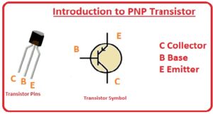
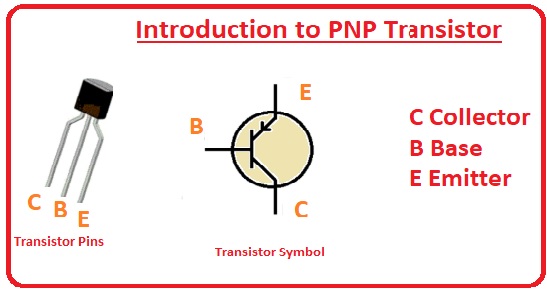
PNP Pinouts
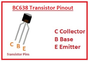
- There is 3 main pinout it has that are explained here.
- Emitter: At this pin, input is provided.
- Base: This pinout is worked as a controller and has a small area than the other two control the current flowing between emitter and collector.
- Collector: This portion has a larger area and output is taken from this component.
PNP Transistor Project Simulation
- PNP Transistor is normally employed as a switch and amplifier in different electronic devices and projects.
- In the case of a switch, it controls all working of the circuitry and as amplifier increases the output value of circuit to required value.
- Here i want to mention that if you are working on this module and want to make an amplifier or switch for your project. You must have proper knowledge of it.
- If you are new to electronics or have less experience with that then you must have to consult with manufacturers that can help you to make your project.
- For this, i recommend your one and only PCBWAY. He is an expert in electronics and also offered the different components related to electronics specially provided different categories of PCB boards that are used in projects with high quality and affordable prices.
- PCBWAY not just help to make projects but also fulfill the all requirements that you asked to add to your projects.
- They also make connections to their clients from start to end of the projects and maintain the level to fulfill the project need.
- They also offered the sponsorship program for the students to make projects you must also their offers. In the end, they are one and all places where you can get all things that you needed for your electronic projects.
Types of PNP transistors
- There are different types of PNP transistors, including those that work by PNP junction, ones that work by NPN junction, and a few that work by odd-quantum rule.
- The types are as follows: PNP junction transistors are the most widely used PNP transistors because they produce a good current performance at relatively low power.
- PNP junction transistors may not work well with doped N-type semiconductor layers, because doped layers tend to heat up, making the transistor conductive, making it wear out sooner.
- Using a PNP junction transistor requires a solid metal barrier between the junction and base. Using doped semiconductors is prone to memory effects, where the transistor does not work correctly because its base temperature is too high.
Applications of PNP Transistors
- Power Supply Circuitry A PNP transistor is useful in making AC power transformers and DC power supplies. Since PNP is a dissimilar and complementary conductor of electricity, it also makes for excellent rectifier circuitry, like the Zener diode.
- PNP rectifiers are often used to cut the high-frequency noise that occurs at high currents like those of a rectifier, allowing for cleaner sounding amplifiers and loudspeakers.
- Radio Circuitry A PNP transistor is useful in making radios that emit electromagnetic waves. It works by sending radio waves between two electrodes of one of the transistor’s terminals.
- Transistors made of PNP material are also used in FM radio receivers. Digital Communications A PNP transistor is useful in digital communications.
That is all about the PNP transistor i have explained all parameters about this module with the details still have any problem plz mention here. I will solve all you queries. Thanks for reading.


