

 Hello, friends, I hope all of you are enjoying your life. In today’s tutorial, I am going to explain Permanent Magnet Synchronous Generator. The synchronous generator is such a device that transforms mechanical energy into the electrical energy delivered by the prime mover of the generator. It is also known as an alternator. It is called a synchronous generator because its rotation speed is equal to the rotating speed of the field at the stator of the generator called synchronous speed. In this generator, an external supply is provided to excite the generator which is the reverse of the induction generator. For excitation, the external DC source is connected to a synchronous generator.
In today’s post, we will have a look at another type of synchronous generator called a permanent magnet synchronous generator. In this generator, there is no need for a separate DC source for the excitation of the generator. We will describe the working principle, applications, advantages, disadvantages, and some other related parameters of this generator. So, let’s get started with the Permanent Magnet Synchronous Generator.
Permanent Magnet Synchronous Generator
- The permanent magnet synchronous generator is called so because in this synchronous generator, excitation is provided with the permanent magnet instead of the external excitation source.
- Its rotor consists of the permanent that generates a field for excitation and replaces the external supply source for the generator.
- In most of generation power plants, the synchronous generator is used. In steam turbines, hydro turbines, and in gas turbines synchronous generator is used.
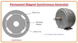
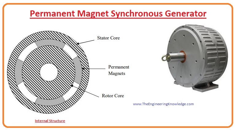
- Like other generators, the physical structure of this generator is the same it also consists of the rotor which also comprises of the permanent magnet with the shaft connected with it.
- Like the stator of other generators, this generator also has a stator that protects the internal structure from the exterior environment.
- In a permanent synchronous generator, there is no need of slip rings and carbon brushes, which makes the machine less expensive, and lightweight, and maintenance of the generator also decreases.
- But in high-rating generators, large-size generators are used to make machines somewhat expensive and increase the price.
- The generator attached to the power electronic conversion circuitry can work at less speed and so there is no need of the gearbox.
- The presence of gearboxes increases the price, energy losses, and cost of repairing the generator but without the gearbox price and weight of circuitry decreases it is also the best option for offshore applications.
- With the direction of flux lines, the permanent synchronous generator is divided into three categories: the radial flux permanent magnet synchronous generator, the second one is axial flux permanent magnet synchronous generator and the transverse flux permanent synchronous generator.
What is Synchronous Speed
- PMSG is called synchronous generators since the voltage produced frequency in the stator or armature calculated in the hertz is directly proportional to the rotation cycles of the rotor.
- The formula to find the synchronous speed is 120 (fe/P).
- In this equation, the fe is the frequency of the voltage induced at the stator.
- P is the no of a pole in the generator.
Working Principle of Permanent Magnet Synchronous Generator
- The working of the PMSG depends on the field produced by the permanent magnet attached at the rotor of the generator for the conversion of mechanical energy into electrical energy.
- Like synchronous generators in PMSG, there are two types of windings first one is the armature that is wound on the stator and the second one is the field winding that is wound on the rotor.
- At the generator’s stator, 6 soils of copper and windings are wound and fixed at their respective places.
- The rotor that has a permanent magnet is connected to the bearing rotating on the shaft. In this generator, there are 2 rotors; the first one is behind the stator, and the second one is at the exterior side.
- Both of these are connected through the long studs moving by the hole in the stator.
- The blades are also surfaced on these studs that connect the rotors.
- These blades rotate the rotor for the production of electrical energy.
Applications of Permanent Synchronous Generator
- These are some applications of the permanent magnet synchronous generator.
- It is used to provide the power for the excitation of the high-rating synchronous generator.
- During the short circuit, these generators provide the power to the generator connected in the system to maintain the required voltage for the system.
- It is also used in such power generation systems where wind turbines are used.
Advantages of Permanent Magnet Synchronous Generator
- High efficiency:
- Less noise and vibration:
- size and lightweight:
- Different speed range:
- Reliable operation:
Disadvantages of Permanent Magnet Synchronous Generator
- Higher initial cost:
- Susceptibility to demagnetize
- Need for a controller:
- Limited availability:
- Poor voltage regulation:
- Sensitive to load changes:
Permanent Magnet Synchronous Generator Vs. Permanent Magnet Synchronous Motor
| Characteristic | Permanent Magnet Synchronous Generator | Permanent Magnet Synchronous Motor (PMSM) |
|---|---|---|
| Function | it converts mechanical energy into electrical energy like other generators | it connects electrical power to mechanical energy |
| Power Output | electrical power produced | it uses electrical power |
| Excitation | excitation is provided by the permanent magnet | From permanent magnet get excitation |
| Stator and Rotor layout | induction generator-like layout | brushless DC motor configuration |
| Control | Output voltage and frequency are externally configured | Speed and torque are controlled through the input voltage and frequency |
| Applications | Wind turbines, hydroelectric power generation | Electric vehicles, industrial devices |
| Power Factor Control | it needed external power factor correction | Can work at a unity power factor |
| Regenerative Capability | it is not regenerative source and needs an outer power supply | it regenerates power during braking or deceleration |
| Efficiency | Larger efficiency at high-speed | for rated speed high efficiency |
| Cooling Requirements | it requires cooling systems | commonly not needed |
Construction of Permanent Magnet Generators
| Part | Description |
|---|---|
| Permanent magnets | it is the main part of this generator since it produces the field that induces the current in its windings |
| Spinning axle | it is the axle that is configured on permanent magnets, is controlled by motor use of other mechanical energy sources |
| Windings | Windings are wounded on the spinning axle. Due to the field current produced in these windings |
| Slip rings | They are configured with the external circuits through windings. it helps current to flow from generators to external connections |
| Brushes | Brushes are connected with slip rings. They carry current from windings to the circuit connected |
Permanent magnet generator vs alternator
| Feature | Permanent Magnet Generator | Alternator |
|---|---|---|
| generator type | it is an AC generator | it also AC generator |
| permanent magnets | Yes it has | it not uses |
| DC excitation circuit | it does not need excitation | Yes it needed |
| Slip rings and brushes | it has | Not needed |
| Efficiency | larger | Low |
| Weight | Less weight | High weight |
| Size | Small size | larger |
| Cost | high prices | Less costly |
| Applications | Wind turbines, electric vehicles, solar panels, | trucks, Cars, motorcycles, boats |
Related posts
Synchronous Generator Equivalent Circuit
Synchronous Generator Phasor Diagram
Synchronous Generator Power and Torque
Synchronous Generator Parameters
Synchronous Generator Operating Alone
Synchronous Generator Parallel Operation
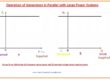
Synchronous Generator parallel with Large Power system
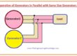
Synchronous Generator Parallel with same Size Generator
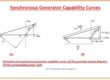
Synchronous Generator Capability Curves
Synchronous Generator Transients
So, friends, that is the detailed post on the permanent magnet synchronous generator I try my level best to simplify this article for you and explain every parameter related to the generator. If you have any further queries about this post as in the comments. I will guide you further. See you in the next tutorial. Thanks for reading.
I like what you guys are usually up too. Such clever work and reporting! Keep up the superb works guys I’ve included you guys to blogroll.
Hello, Great to read your articles and discussions about Permanent Magnet Generators. Thank you for those.
I am an “inventor” with a multitude of practical and theoretical skills.
I am building a micro hydro water turbine in the hills to produce 3 – 5 Kw of electricity off grid.
The hydraulic system is in place and I have purchased a three phase 380v Permanent Magnet Alternator. The system is to run into purpose designed house heating system consisting of a 1.5kW heat pump and switched domestic heaters. These were to 240v. Single phase to be derived from rectified three phase to 380v DC into a 3 and 2 kw sine wave inverters. to 240v AC.
So I need controllers. to maintain the speed of PMA rotation to the given voltage output.
Then the challenge for the design. Resistive load present no real problem but the heat pump compressor will present on starting- loading issues particularly if in single phase.
So now I am thinking about using a three phase compressor. (A local refrigeration company are to construct a bespoke machine).
If I stay in three phase I will have less losses and the system should be the most resilient to the high milli second loading currents and not stress the sine wave inverter.
If I were to change generator to use a synchronous induction generator with AGC the output voltage and frequency would be automatically controlled and maintained.
But I already have the PMA (suitable for a wind turbine etc) which is classic in internal wiring configuration Star / Delta.
So thanks for reading the long introduction. So at last here is the real question.
Can this alternator be controlled with any kind of constructed AGC with feed back to maintain the frequency as well as the output voltage particularly in the miili-second compressor start up times.
I don’t think the speed variation controller that I will build to switch solid state relays to the resistive loads will react fast enough due to the flywheel effects of the hydraulic system.
I really welcome your advice if you can.
Many thanks.
Very interesting, I need a generator domestic use to provide dc generation supplying a battery pack holding a 20kw capacity via inverter. Where can I buy these ? Any different sizes?