 A Passive Attenuator is a bidirectional electronic circuit that comes with resistance as the main component. Attenuators are 2-pin resistive circuits that are used for delivering power in the circuit where the load is connected.
A passive attenuator reduces the amount of power delivered to the load. Attenuators are used on wireless systems where weak signal strength is increased through the use of attenuators.
The passive attenuator is a passive resistive system used for different electronic devices to weaken signal levels through enhancing impedance match, in another word it works as the reverse function of amplifiers
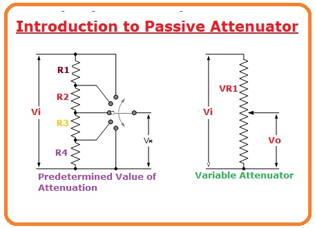
Introduction to Passive Attenuator
- Passive attenuators a bidirectional electronic circuits that are made with the use of resistances.
- It is an opposite circuit of amplifiers where reduces gain through resistive voltatge operator circuit as part of the attenuator.
- The quantity of attenuation is measured with the output-to-input ratio taken.
- Such as if there is an input voltage of a single volt and the output voltage is one millivolt then the attenuation value is 1mV/1V to 0.001.
- Some factors used for considering voltage, current to power used for attenuation as passive resistive component called attenuation factor,
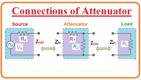
Connections of Attenuator
- The attenuator circuit is used to provide stable attenuation or offers varied attenuation in pre-measured phases.
- Normally static attenuator system is defined as an attenuator pad that can access for accurate standard from 0 decibels higher than one hundred dB.
- Variable and switched attenuators are adjustable resistance circuits that define an increase in attenuation for switched steps such as -2dB or -6dB per switch position.
- The attenuator is 4 four-walled passive resistive system made for providing distortionless attenuation of output signals for different frequency values..
What is an Attenuation degree?
- The attenuator’s working is defined through input signal decibels number reduces per frequent decade. The decibel is defined as a logarithm-measured voltage, current, or power ratio and is denoted 1/10th of a Bel (B). In other words, it takes 10 decibels to make one Bel.
- The ratio between the input signal and output signal is defined as
dBv = 20log10 (dB)
- We can see in the above-given equation that the decibel (dB) is a logarithmic proportion and so it has no units.
- In passive attenuator circuitries, it is frequently suitable to allocate the input assessment as the 0 dB reference.
How to make Switch Attenuators
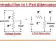
- There are differnt methods where resistors can connected for attenuators a potential divider circuit is a simple type of passive attenuator circuit.
- The potential or voltage divider circuit is called an L pad attenuator since its circuit is like an inverted L shape.
- There are some other type of attenuator circuits exists like T pad attenuators and Pi Pad attenuator based on connections.
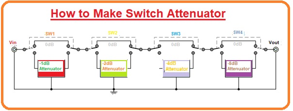
Switch Attenuator
- 4 independent resistive attenuator systems have switch connections in the series ladder system with every attenuator coming with a double-value predecessor, (1-2-4-8).
- Every attenuator system can be in or out switch configuration of the signal path since needed with connected switch generating varying attenuators circuit has features to switch from 0dB to -15dB in 1dB steps.
- So total amount of attenuation given by the circuit is the summation of 4 attenuator systems that connected IN.
Features of Attenuator
- It is a resistive system used for certain attenuation values. Like a fixed attenuator but comes with push button for choosing pre-calibrated steps. Helps manual setting in a defined range.
- It can regulated with an external computer signal with adjusting attenuation
Applications of Passive Attenuator
- The passive attenuator decreases power provided to connected load through a single fixed value, variable quantity, or in a series of known switchable steps.
- Attenuators are used in communication circuits, radio systems, and transmission line features for reduce stronger signals.
Faqs
What are the advantages of attenuators?
- It is used for reducing signal amplitude, which is its basic application of attenuators do.
- It is used for controlling signal amplitude, where variable RF attenuators are used for dial-in signals to the required amplitude.
What is the working principle of attenuators?
- The basic function of an attenuator is that it weakens the high-level output of signal generators to provide lower-level signals like the antenna input of a sensitive radio receiver. The attenuator can be in signal generators or stand-alone devices.
What are the three types of attenuators?
- It is a resistor system set to a certain attenuation point.
Step
- It has circuit like fixed attenuators but comes with a push button for choosing pre-calibrated points
Continuously Variable
- It provides a manual setting in a defined range
What are the properties of the attenuator?
- Attenuators are used for reducing signal levels. here power dissipation of devices is based on surface area and resistance material mass. Its main features are RF attenuators has high accuracy, low SWR, and provide repeatability.
What are the disadvantages of attenuation?
- The main limitation is the loss of signal since that causes improper signal quality and data losses. Increases in working cost since more circuits such as amplifiers, repeaters, or signal boosters cover signal losses
What are the principles of attenuation?
- The amplitude and intensity of ultrasound signals reduce since they move through tissue the process called attenuation.
- Providing fixed propagation distance, attenuation has an effect on high-frequency ultrasound waves for larger degrees as compared to low frequency.
What is the frequency range of attenuators?
- Attenuators are made to reduce the power of the signal with less effect of signal. The attenuation value varies from 0 dB to 69 dB with a frequency value of 0 to 86 GHz.
Do attenuators reduce noise?
- Attenuators can used for reducing both output power and output noise signal generator. But it not have features to attenuate signals less than noise floor (thermal noise) at -174 dBm/Hz.
Read also:
In the coming tutorial related to Attenuators, we will discuss the L-type attenuator system.