O-rings are commonly used as sealing components in various industries, including medical and automotive. It comes with simple design configurations, that is, a circular ring having a cross-section, for controlling leakage of gases and liquids. For proper sealing, use an accurate O-ring size. In this tutorial, we will cover detailed features for the O-ring and explain the O-ring size chart. So let’s get started.
What Are O-Rings?
O-rings are a mechanical gasket design, such as a torus, that is constructed with elastomeric materials. If compressed between two locations, they make a tight seal for controlling gases or fluid leakage.
O-rings are part of different projects for industries. Mostly, it is seen in automobile engines and braking systems, for oil and heat resistance make safe vehicle.
In electronic devices, O-rings protect from dust and water effects
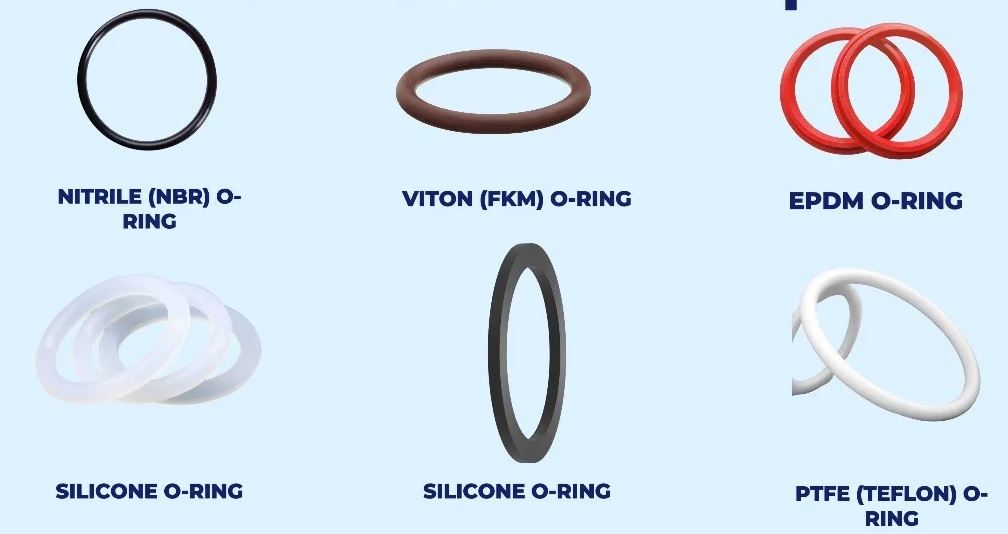
How to Measure O Ring Size
Read also : Oxygen Tank Size Chart:
O-ring measurements are important for the replacement of different components. Follow these points for measurements of O-ring size.
Tool selection:
A digital caliper is used for measuring internal diameter and cross-section. In high-volume operations, cone gauges make it easy requirement of standard sizes.
Inside Diameter calculations
Put the O-ring flat on a non-deformable surface and measure the internal circle diameter without stretching. Note the given measurements in inches or millimeters.
Cross-Section
Now calculate the O-ring toroidal section thickness and get different readings to consider wear and also manufacturing changes
Verification with Chart values
- Compare measured values with O-ring size chart
Stretch measurement:
- if o rings used get details of stretching or compression also calculated in relax conditons
Standard AS568 O-Ring Size Chart
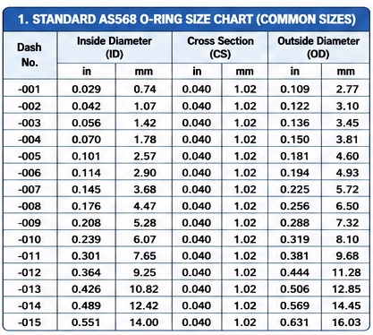
| Dash No. | Inside Diameter (ID) in | Cross Section (CS) in | Outside Diameter (OD) in | ID (mm) | CS (mm) | OD (mm) |
| -1 | 0.029 | 0.04 | 0.109 | 0.74 | 1.02 | 2.77 |
| -2 | 0.042 | 0.04 | 0.122 | 1.07 | 1.02 | 3.1 |
| -3 | 0.056 | 0.04 | 0.136 | 1.42 | 1.02 | 3.45 |
| -4 | 0.07 | 0.04 | 0.15 | 1.78 | 1.02 | 3.81 |
| -5 | 0.101 | 0.04 | 0.181 | 2.57 | 1.02 | 4.6 |
| -6 | 0.114 | 0.04 | 0.194 | 2.9 | 1.02 | 4.93 |
| -7 | 0.145 | 0.04 | 0.225 | 3.68 | 1.02 | 5.72 |
| -8 | 0.176 | 0.04 | 0.256 | 4.47 | 1.02 | 6.5 |
| -9 | 0.208 | 0.04 | 0.288 | 5.28 | 1.02 | 7.32 |
| -10 | 0.239 | 0.04 | 0.319 | 6.07 | 1.02 | 8.1 |
| -11 | 0.301 | 0.04 | 0.381 | 7.65 | 1.02 | 9.68 |
| -12 | 0.364 | 0.04 | 0.444 | 9.25 | 1.02 | 11.28 |
| -13 | 0.426 | 0.04 | 0.506 | 10.82 | 1.02 | 12.85 |
| -14 | 0.489 | 0.04 | 0.569 | 12.42 | 1.02 | 14.45 |
| -15 | 0.551 | 0.04 | 0.631 | 14 | 1.02 | 16.03 |
Metric O-Ring Size Chart
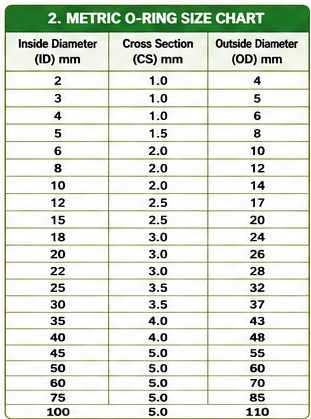
| Inside Diameter (mm) | Cross Section (mm) | Outside Diameter (mm) |
| 2 | 1 | 4 |
| 3 | 1 | 5 |
| 4 | 1 | 6 |
| 5 | 1.5 | 8 |
| 6 | 2 | 10 |
| 8 | 2 | 12 |
| 10 | 2 | 14 |
| 12 | 2.5 | 17 |
| 15 | 2.5 | 20 |
| 18 | 3 | 24 |
| 20 | 3 | 26 |
| 22 | 3 | 28 |
| 25 | 3.5 | 32 |
| 30 | 3.5 | 37 |
| 35 | 4 | 43 |
| 40 | 4 | 48 |
| 45 | 5 | 55 |
| 50 | 5 | 60 |
| 60 | 5 | 70 |
| 75 | 5 | 85 |
| 100 | 5 | 110 |
Standard O-Ring Cross Section Chart
| Cross Section (mm) | Cross Section (in) | Applications |
| 1 | 0.04 | Electronics |
| 1.5 | 0.059 | Medical Equipment |
| 2 | 0.079 | Pneumatic Systems |
| 2.5 | 0.098 | General Machinery |
| 3 | 0.118 | Hydraulic Systems |
| 3.5 | 0.138 | Pumps |
| 4 | 0.157 | Industrial Equipment |
| 5 | 0.197 | Heavy Machinery |
| 5.5 | 0.217 | Large Flanges |
| 6 | 0.236 | High Pressure Systems |
| 7 | 0.276 | Mining Equipment |
| 8 | 0.315 | Large Industrial Seals |
O-Ring Groove Size Chart
| O-Ring Cross Section (mm) | Groove Width (mm) | Groove Depth (mm) |
| 1 | 1.3 | 0.75 |
| 1.5 | 1.9 | 1.15 |
| 2 | 2.5 | 1.55 |
| 2.5 | 3.1 | 1.95 |
| 3 | 3.7 | 2.35 |
| 3.5 | 4.3 | 2.75 |
| 4 | 4.9 | 3.1 |
| 5 | 6 | 3.85 |
| 5.5 | 6.6 | 4.25 |
| 6 | 7.2 | 4.65 |
O-Ring Material Temperature Chart
| Material | Minimum | Maximum |
| NBR (Buna-N) | -40°C | 120°C |
| EPDM | -50°C | 150°C |
| Silicone (VMQ) | -60°C | 230°C |
| Viton (FKM) | -20°C | 250°C |
| HNBR | -40°C | 150°C |
| Neoprene | -40°C | 120°C |
| Polyurethane | -35°C | 90°C |
| PTFE | -200°C | 260°C |
O-Ring Material Hardness Chart
| Shore A | Hardness Details | Use |
| 50 | Very Soft | Low Pressure |
| 60 | Soft | Static Seals |
| 70 | Standard | General Purpose |
| 75 | Medium Hard | Hydraulic |
| 80 | Hard | Pneumatic |
| 90 | Very Hard | High Pressure |
| 95 | Extra Hard | Backup Rings |
Metric to Inch Conversion Chart
| Metric (mm) | Inches |
| 1 | 0.039 |
| 1.5 | 0.059 |
| 2 | 0.079 |
| 2.5 | 0.098 |
| 3 | 0.118 |
| 3.5 | 0.138 |
| 4 | 0.157 |
| 5 | 0.197 |
| 6 | 0.236 |
| 8 | 0.315 |
| 10 | 0.394 |
O Ring Sizing Importance
Use of proper O-ring dimensions makes a proper seal during reliable working in high pressure, facing temperature, and chemicals. An O-ring with small-sized faces that stretches too much causes damage.
While oversized, it does not have accurate sealing, causing leaking.
The cross-section also affects how the O-ring compresses and seals. Different projects use a certain cross-section for handling pressure
Metric vs. Standard O-Ring Sizes
The AS568 standard and metric each come with certain industries. AS568 standards are normally used in the USA which employs imperial units for O-ring dimensions.
They provide more than 400 standard sizes of the O-ring size chart for accurate working in the vehicle industry.
Metric O-rings are employed in international markets with the millimeter standard. A metric O-ring equal to AS568-012 comes with an inside diameter of 9.25 mm and a CS value of 1.78 mm.
O-ring Sizes and Tolerances: Standard Sizes
O-ring standard size used by different O-ring manufacturers based on Aerospace Standard AS568B,
Aerospace Size Standard for O-rings.These details given by the Society of Automotive Engineers (SAE) define sizes of O-rings in a group of 6, also in inches or millimeters. The first five in the group were configured on a cross-sectional diameter.
The 6th series has 20 size values for boss seals. Standardized sizes are part of military projects.
Cross-sectional diameter values in the range of 0.040 to 0.275 inches. Internal diameter comes in the range of 0.029 to 25.940 inches.
O Ring Metric Sizes
Standard metric size used for O-rings are based on the International Standard ISO 3601-1:2002: fluid power system o-rings, inside diameter, tolerances, cross-sections, and accurate size recognition code.
That standard groups metric sizes in two series, G and A. The G series is part of general-purpose projects and comes with different inside-diameter values.
A series is used in aviation projects where tight tolerance is preferred. The G series comes with the 445 series, and the A series offers 383 sizes.
The International Organization for Standardization (ISO) issued ISO 3601-1 in 1978 and revised it in 1988 and 2002.
One more important revision was made for ISO size configuration to sizes with
Another major aerospace standard, AS568B, now ISO-568B, does not employ the dash number system as
Currently, ISO sizes do not use a dash for the Aerospace Standard.