A multilayer ceramic capacitor, or MLCC, is a non-polarized ceramic capacitor constructed with stacked ceramic dielectric layers with inner metallic electrodes. Its layered design increases capacitance with compact SMD packaging, so it is easily connected on PCB boards. Multiple ceramic capacitors are employed for different functions, such as RF circuits, power decoupling, filtering, etc.
In this study, we will cover details of the features of multilayer ceramic capacitors and their importance for electronic circuits. So let’s get started
What Is a Multilayer Ceramic Capacitor?
A multilayer ceramic capacitor is part of a capacitor composed of different ceramic layers that work as a dielectric. These capacitors are basically single-layer capacitors stacked in single packages.
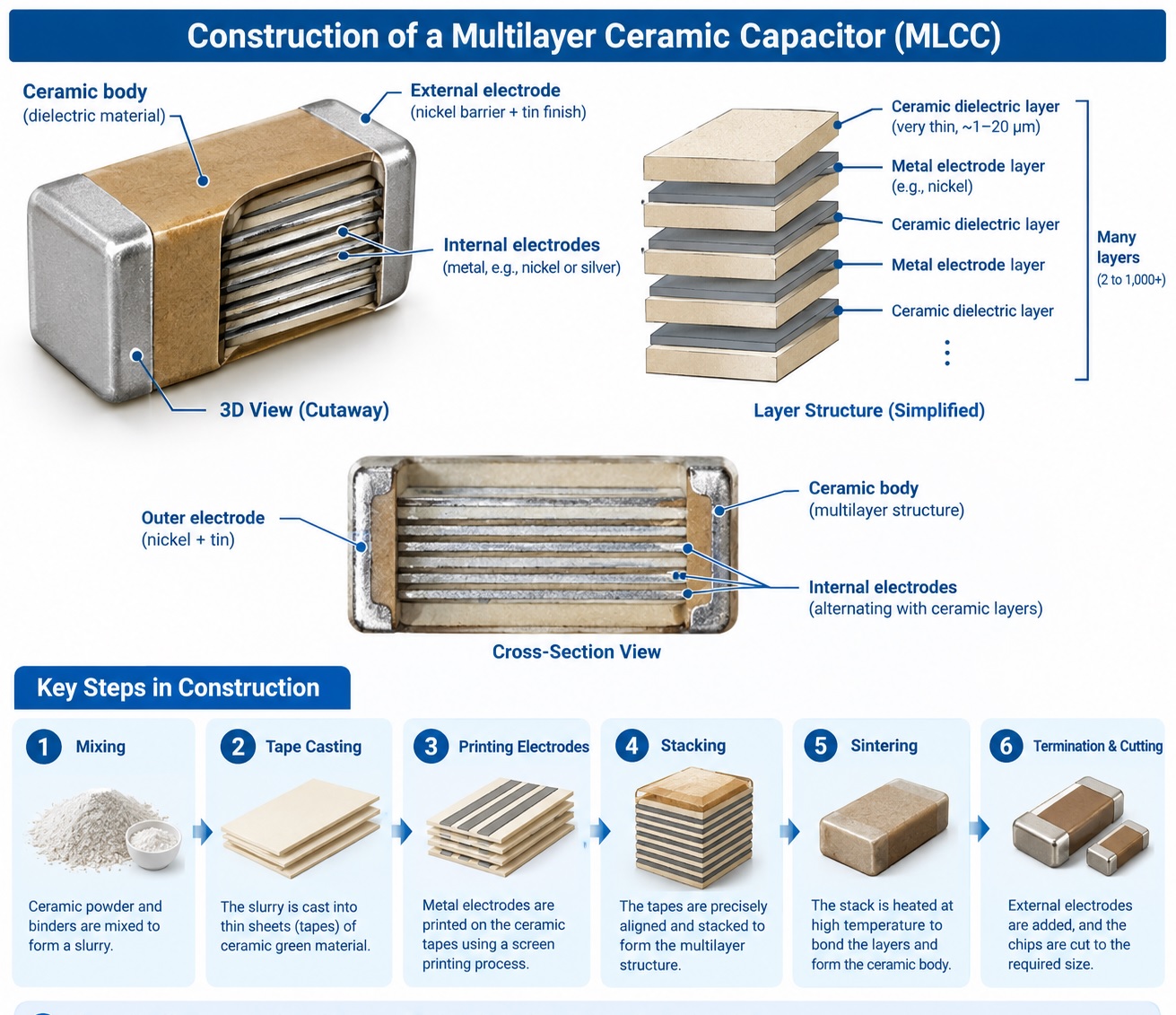
Construction of MLCC composites with multiple metallic electrode layers and dielectric ceramic layers.
This capacitor gets charged and discharged for a short time. Its main features are providing current flow regulation and controlling electromagnetic interference of components.
In this capacitor, single dielectric thickness and stacked layer numbers are directly proportional to the capacitance of this capacitor.
To make each layer thin, a different process is applied for stacking more layers to make ultra-small, high-capacity capacitors.
This multiple-layer structure increases capacity with the same dimensions and is used in applications where speed is restricted
Their compact design and non-polarized behavior, at high frequencies, make them useful for different applications such as industrial control, the vehicle industry, communication devices, and power supply
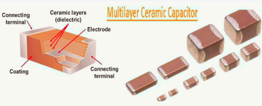
Construction of a Multilayer Ceramic Capacitor
MLCC is like a small parallel plate capacitor configured in one assembly. The structure of an MLCC is.
Multilayer ceramic capacitor has a strong structure, a metallic component constructed with ceramic dielectric layers and metallic electrodes in alternative configuration.
Electrode layers, such as configured electrodes, make connections at opposite points alternatively.
Small capacitors, like assemblies, are obtained with each electrode pair since internal capacitors connected in a parallel configuration have a very high overall capacitance according to layers and electrodes
The ends of the capacitor are metallic-coated points, and their plating makes a solderable area. In new technology, nickel internal electrodes have been used since the introduction of bulk construction
How to Manufacture MLCC
A proper binder helps thin ceramic foil with powder suspension. same-size sheet cut from foil rolls that screen print through metallic paste that are electrode.
With automated techniques, sheets stacked with the required layers are made solid. Electrodes stacked in an alternative way with space for alternative layer connections. Stacked, layered, pressed and cut into single pieces.
This process demands high accuracy for bulk layers. Since this capacitor comes with a different number of layers according to the requirements of voltage and capacitance
When cutting finished stacks, burn through the binder. that occurs with sintering at around 1200 degrees centigrade temprature make crystalline structure.
Burning gives the required dielectric features. After burning, a cleaning process is performed, then metallisation. After that, layered, stacked and compressed. With metallisation, electrodes are connected in a parallel configuration and form capacitor terminals.
Since these capacitors lead less, they are small in size. They do not need through-holes for PCB board mounting configured with machines. that make some components low cost
How MLCC works
After applying voltage to capacitors, reverse charges store over internal electrodes. Ceramic dielectric exists between electrodes and stores energy in the form of an electric field.
Internal layers are connected in parallel; the capacitor has features for storing charge in its structure.
When the DC supply capacitor draws zero leakage current. But when connected, charging and discharging occur fast, which is used for decoupling and filtering.
Low series resistance and low equivalent series inductance of a capacitor are best for high-frequency noise and high-speed load transients.
MLCC CEMS with self-resonant frequency: if the value is less than the frequency, it functions like a capacitor. for high-frequency parasite inductance work, and work like an inductor. This feature helps minimize impedance at higher frequency values
MLCC Dielectric Types
Commonly used dielectrics for capacitors are
| Dielectric | Characteristic | uses |
| C0G / NP0 | Very stable, low loss | RF, precision filtering, resonant circuits |
| X7R | High capacitance density | Decoupling and power filtering |
| X5R | High capacitance density for compact packages | Low-voltage power rails and portable electronics |
| Y5V / Z5U | high nominal capacitance, poorer stability | Limited non-precision applications |
Multilayer Ceramic Capacitors Electrical Characteristics
Some important characteristics are
Capacitance
The MLCC capacitor is defined based on the datasheet conditions and the NRMAY for room temperature for zero DC biasing. The datasheet does not provide the effective capacitance of the circuit. A normal value of tolerance exists, such as
| Dielectric Type | Capacitance Tolerance |
|---|---|
| C0G / NP0 | ±1%, ±2%, ±5% |
| X7R | ±10%, ±20% |
| X5R | ±10%, ±20% |
Arguerance accepted for decoupling and filtering. In timing, radio frequency, and high-accuracy analog circuits, stable direct current is used.
Voltage
MLCCs come with different voltage ratings and may range from 6.3 V up to 100 V or higher. Common design features are to use a voltage rating 1.5× to 2× higher than the highest operating voltage.
High voltage rating minimizes DC bias capacitance losses and the electric field for long-term reliability
Temperature
Temperature value is based on the dielectric code. C0G / NP0 MLCCs are stable for different temperature values. But X7R and X5R capacitors offer high capacitance changes with high capacitance density.
For small-level X5R used in industries, vehicles, and high-temperature X7R, X8R, and MLCCs used
ESR and ESL
This capacitor shows lower ESR and ESL values than different electrolytic and tantalum capacitors.
Low ESR minimizes resistance losses, and lower ESL helps the capacitor respond quickly to switching noise.
So MLCCs are used close to IC power pins, regulators, and high-speed digital circuits. But in some conditions, LWESR can cause resonance errors, so damping is used with MLCCs.
Frequency Response
This capacitor also has a self-resonant frequency where capacitive reactance and parasitic inductance cancel out.
MLCC acts like a capacitor below the self-resonant frequency and works as an inductor at high frequencies.
Small packages have lower equivalent series inductance (ESL) and a high self-resonant frequency. Larger packages provide high capacity but don’t work well for high frequencies.
So some structures offer variable values and package sizes, for example, 100 NF CSEs to IC pins.
Leakage and Dielectric Absorption
MLCC CMEs with low leakage current and are part of battery operating circuits. Dielectric absorption is low for C0G/NP0 parts.
In analog design, C0G is used compared to X7R or X5R.