 Hello, readers welcome to new post. Here we will cover the Introduction to TP5000 Switching Battery Charger. It lithium battery charger consists of one cell. In this module there is switching charger exists that indicates has ability to give high value of current with efficiency at one time. There are different specifications has this board such as undervoltage operation, overcurrent, and temperatures.
In this post, we will discuss different feature parameters and some other points of this board. So let’s get started Introduction to the TP5000 Switching Battery Charger.
Introduction to TP5000 Switching Battery Charger
- TP500 switching module consists of one manganese lithium battery for charging the devices.
- It comes with a QFN16 ultra-compact structure having simple circuitry making the board effective for different small device charging boards.
- Its main features are to handle short circuits, battery temperature control, high temperatures to the circuit, and battery protection.
- It comes with different input voltage values categorized into three types that are trickle pre-charge, contact volts trickle charge containing current, and its maximum charging current value is two ampers.
- Its operating frequency value is eight hundred kilohertz which prefer to use in small-sized devices.
- There is no need for an anti-intrusion protection Schottky diode for this module since consists of PMOSFET anti-intrusion circuitry.
TP5000 Switching Battery Charger Features
- The main features of TP5000 are explained here
- It consists of one manganese 4.2-volt cell
- Consis of MOSFET used for switching
- Its structure is simple and makes less heat
- Its programmable charge current value is 0.1 ampers to two campers
- The operating volts value is up to nine volts
- It has 2 LEDs to indicate the status
- Has the ability o handle undervolted protection, overcurrent, and temperatures
- The frequency value is eight hundred kilohertz
- Gets automatic charging
- Comes in QFN packaging and 4mm by 4mm dimensions
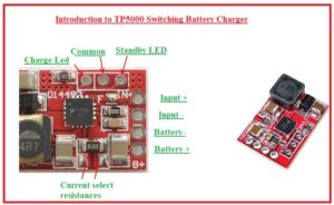
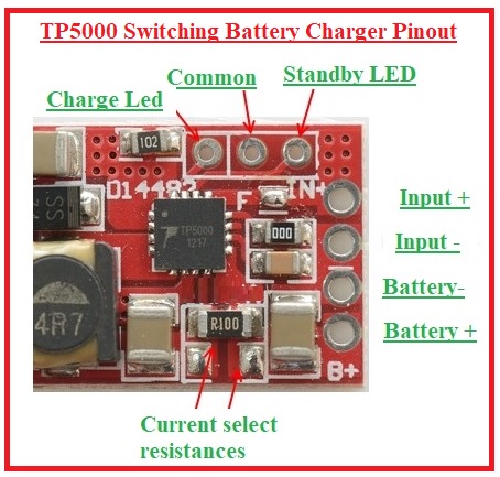
TP5000 Switching Battery Charger Pinout
- The main pinout is explained here
- Vin pins are 1,2, and 16 used to give power to the board
- 3, 4, 5 LX that are drain pins of inner built MOSFET
- 6, 7 are ground pins
- 8 is Vs and used for current sensing
- 9 is BAT used for volts sensing
- 10 is VREG gives inner volts to the board
- 11 Ts battery temperatures control pins
- 12 is Rtrick used for trickle charge current adjustment
TP5000 Switching Battery Charger Applications
- All applications of TP5000 are explained here
- It used in LED drivers of white colors
- Used in handheld devices like phones, and Media players
- Used in different electrical devices
TP5000 Working

- The working of TP5000 is based on the integration of battery charging integrated circuits. It is made on a switching buck converter that has features for handling high currents with efficiency and without producing heat as other ICs do.
- The 800Khz switching frequency helps to use small inductors with a range of 2.2uH to 10uH.
- Lithium-ion and lithium-iron phosphate batteries can charged with this integrated circuit. They come with different nominal voltages and also different voltage features. It is defined with accurate pushing pin CS.
- For lipo charging open drain output can used for pulling the pin low directly. The 10K resistors must connected between VIN and CS if li-fe-po charging is needed.
- Value of shunt resistor connected between VS and BAT used for setting charging current. The required shunt resistance is 0.1V/Iout when the current is the limited threshold of 100mV.
- The shunt resistance of 500m is used for the highest output of two ampers.
- The trickle charge is the value of charging current for maximum conditions. If the RTRICK pin is short-circuit with ground trickle current will be ten percent of the charging current. and for floating conditions will be 100%.
Read also
What is a switching battery charger?
- Switching battery charges comes with standalone functions and features an inductor circuit that helps high voltage and high current with high-efficiency charging.
What is the input voltage of TP5000?
- The input voltage value of this module is about DC 4.5V – 9V
What is the switch mode power supply battery charger?
- Switched mode power supply called switch mode power supply is the main powerhouse of effective power transformation getting main voltage AC input and transforming to low voltage DC output.
Read also
That is all about the TP5000 Switching Battery Charger all details has been explained. IF you have any further queries ask in the comments. Thanks for reading have a good day.