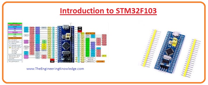
Hello, friends, I hope you all are having fun in your life. In today’s tutorial, we have a detailed look at Introduction to STM32F103. This module is compatible with the ARM Cortex M3 and based on thirty-two bits RISC core which functions at seventy-two megahertz frequency. This device also comprises of twelve-bit analog-to-digital converter, and 3 sixteen-bit timers with a single pulse width modulation timer.
This controller is also compatible with different types of communication protocols such as I2C, and SPI USART. In today’s post, we will have a detailed look at its working, pinout, features, operation, and some other parameters. So let’s get started with Introduction to STM32F103.
Introduction to STM32F103
- The STM32F103 is a high-performance thirty-two-bit RISC-based controller having an operating frequency of seventy-two hertz.
- It has a flash memory of having space of one twenty kilobytes and a static ram of twenty-kilo bytes.
- There are numerous inputs and outputs terminals and different devices linked with the 2 APB buses.
- Every linked device has a 12 bit analog to digital converter, 3 general-purpose sixteen-bit timers.
- This module offers different types of communication protocol which comprises of 2 I2C protocols, 2 SPI, 3 USART communication protocols.
- The functioning voltage of these modules is in the range of two volts to 3.6 volts.
- This module can function in between 2 temperature ranges first is from minus forty to plus eighty-five centigrade and the second one is minus forty to plus one hundred five centigrade.
- The STM32F103xx series is available in different packaging which has thirty-six to one hundred pinouts.
- This module is used in different types of games, GPS, industrial machines, PLC, etc.
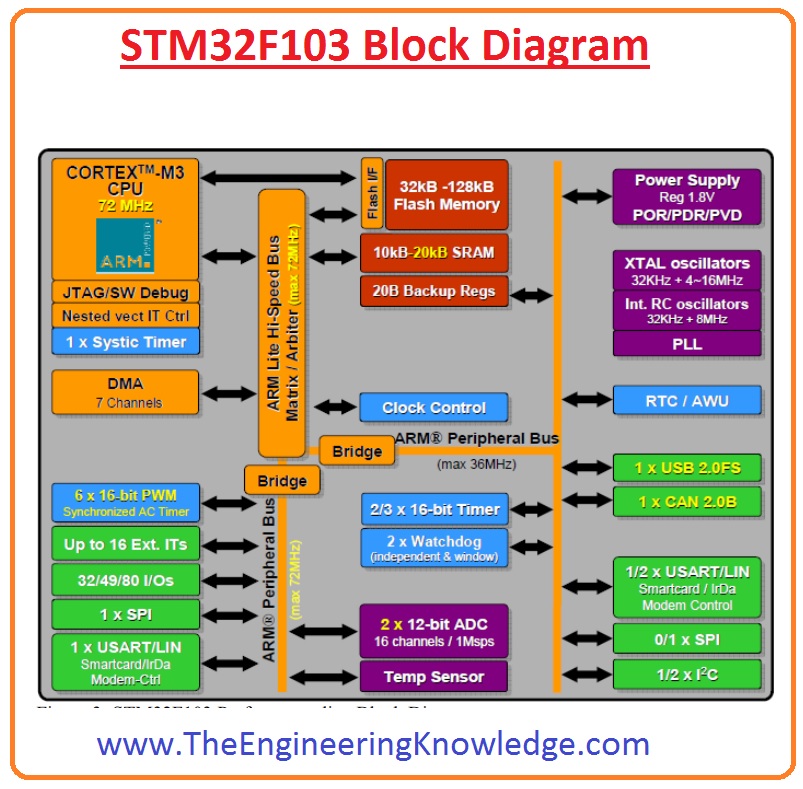
STM32F103 Block Diagram
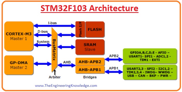
STM32F103 Architecture
- The structure of this module comprises of buses, DMA or direct memory access, inner static random access memory unit inner flash memory which operates as a master device, and all other devices linked with it, slaves.
- The below figure shows the bus architecture of this module. You can see that the connection between the core bus system and direct memory access is regulated by the bus matrix.
ARM Cortex-M3 core
- It is the central processing unit of the controller and it is the main part of the controller. It is the latest model of ARM processor which used in different types of embedded systems.
- This module has seventy-two megahertz highest frequency, ninety DIMPS having 1.25 DIMPS/megahertz,
Memory system
- There are 2 types of memory unit exits in this module first one is flash memory and the second one is static random memory.
- The function if flash memory is to store data and program and its storage range is one twenty kilobytes.
- The static random access memory is used for reading and writing at the central processing unit.
NVIC
- It stands for a nested vector interrupt controller, which is used to regulate the almost forty-three maskable interrupt channels that can be controlled by the programmers, and in NVIC there is sixteen priority programmable levels exist.
EXTI
- Its full form is external interrupt it comprises 19 edge detector lines for creation interrupt requests.
- For detection, purpose exterior trigger is used like rising, and falling triggers.
Clock system
- The clock system of this module comprises different clock sources in the controller like a high-speed inner clock, high-speed exterior clock, phase-locked loop clock, etc.loop) clock, and LSI RC (Low-Speed Internal Resistor and
Capacitor oscillator) and LSE (Low-Speed External) Oscillator.
Startup clock
- This system provides a clock pulse to the controller at the starting time. This startup clock is created through the HSI has a frequency range of eight megahertz.
Power Supply
- There are 3 types of pinouts is used to deliver power to the controller.
VDD
- This pinout is used to offer power to the inputs and output and inner voltage regulation. At this pinout, two to 3.6 volts are given.
VSSA, VDDA
- These pinouts are used for exterior analog power to the analog-to-digital converter the voltage given at these pins are 2 to 3.6 volts.
VBAT
- This pinout is used to offer power to the real-time clock, inner clock oscillator, and registers.
Timers:
- ten16-bit timers come with 4 I2C/OC/PWM counters and quadrature encoder input.
- 2×16-bit motor control PWM timers
- 2×16-bit basic timers used for DAC functions
- 2 watchdog timers
- SysTick timer 24-bit down counter
communication interfaces:
- 2 I2C interfaces
- 5 USARTs
- 3 SPIs (18 Mbit/s),
- CRC calculation unit, 96-bit unique ID
- CAN interface (2.0B Active)
- USB 2.0 full-speed interface
- SDIO interface
Memory:
- 256KB to 512KB flash Memory
- 64KB of SRAM. Supported Flash, NOR, SRAM, PSRAM, and NAND memories.
- LCD parallel interface, 8080/6800 modes.
Power management:
- 2.0V to 3.6V and I/O,PDR, POR, and (PVD),
- 4 to 16MHz crystal oscillator
- 32kHz oscillator for RTC with calibration.
- calibrated internal 40kHz RC
- internal 8MHz factory-trimmed RC

STM32f401 vs STM32f103
| Features | STM32F401 | STM32F103 |
| Architecture | ARM Cortex-M4 | ARM Cortex-M3 |
| Clock Speed | 84 MHz | 72 MHz |
| USB | 1 x Full-speed | 1 x Full-speed |
| Operating Voltage | 1.7 to 3.6 V | 2.0 to 3.6 V |
| Package | LQFP64, UFBGA144 LQFP100, LQFP144, | LQFP64, , UFBGA100, UFBGA144 LQFP100, LQFP144 |
| Flash Memory | 256 KB | 512 KB |
| SRAM | 64 KB | 64 KB |
| DMA Channels | 12 | 7 |
| ADC Channels | 10 | 16 |
| Timers | 14 | 15 |
STM32F103 Technical Features
- This controller is made by STMicroelectronics and it is ARM Microcontrollers – MCU
- It comes with the mounting configuration of SMD/SMT and the Package/Case is LQFP-144
- It comes with a Core of ARM Cortex M3
- Program Memory Size for this module is 512KB and Data Bus Width is 32-bit
- It has ADC Resolution about 12 bit
- The Max Clock Frequency is 72 MHz and has an Input/Output of 112
- Data RAM Size is 64KB
- Operating Temperature is -40 Celsius to +85 Celsius
- SRAM is used as data RAM and interfacing is CAN, I2C, SPI, USART, USB
- The number of ADC Channels is 16 with the Number of Timer/Counter is 8 timers
- Height: 1.4mm, Length: 20mm and Width: 20mm
Pinout of STM32F103
- The pinout configuration of this module is shown in the below figure.
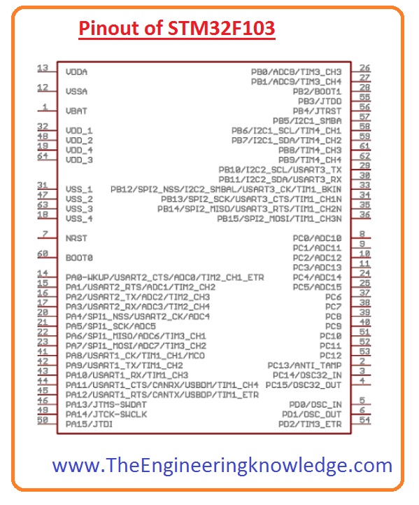
- STM32F103 pinouts are configured in different ports such asPORT A, PORT B, and PORT C
- 37 GPIO pins in PRTA have 16 pins, PORTB has 16 pins PORTC comes with 3 pins and PORTD has 2 pinout.
- Each GPIO port comes with two 32-bit registers (GPIOx_CRL, GPIOx_CRH), a 16-bit reset register (GPIOx_BRR) two 32-bit data registers (GPIOx_IDR, GPIOx_ODR), a 32-bit set/reset register (GPIOx_BSRR), and a 32-bit locking register (GPIOx_LCKR).
- X in the name of registers is used for the port where the pin belongs. If you are using Pin PA1 and have PORTA then registers are GPIOA_CRL, etc.
Faqs
How many pins does STM32F103 have?
- STM32F103 comes with 64 pin package.
What is the voltage of STM32F103?
- It comes with 3.3V I/O.
What is the power consumption of STM32F103?
- Typical values of power consumption is 5.5mA and 3.9mA
What is the speed of STM32F103?
That is all about STM32F103 if you have further queries ask in the comments. Thanks for reading. have a good day.