 Hello, readers welcome to the new post. Today we will discuss Introduction to SP3485. It is a low-power half-duplex transceiver module that has a voltage value of 3.3 volts. It has compatibility with RS-485 and RS-422 protocols. It has pin-to-pin compatibility with Maxlinear SP481 SP485 and SP483 with commonly used industry standards.
It also has compatibility with electrical features of RS-485 and RS422 serial protocols up to 10 Mbps load conditions. In this post, we will discuss different parameters related to this mode so let’s get started with Introduction to SP3485
Introduction to SP3485
- SP3485 is a lower-power consumer transceiver module that has complete compatibility with TIA/EIA-485 standards.
- It consists of a driver and receiver circuit that have their independent enabled and disabled system
- If both modules are disabled both driver and receiver have high input impedance.
- The SP4485 consists of a 1/9 load which permits 256 SP3485 transceivers to be linked with a similar communication protocol.
- The transfer of data speed is about 12Mbps without any error. The operating volts for this module are 3.6 volts.
- It has over-temperature protection, current limit protection, overvoltage protection, and some other functions
SP3485 Features
- It comes with driver output short circuit protection.
- It has compatibility with 75176 industrial standard
- It permits the thirty-two transceivers at the serial bus
- It has -7V to +12V common mode input voltage range
- It has enabled driver and receiver
- Can be configured with five volts supply
- it is RS-485 and RS-422 transceiver
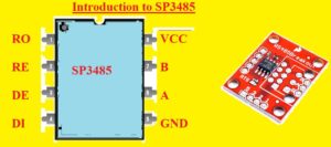
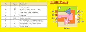
SP3485 Pinout
- It has eight pinouts that are discussed here
- RO: It is receiving output
- RE: It received output enable active low
- DI: Driver input
- GND: Used to make connections with the ground
- A: Non-inverting driver output or receiver input
- B: Inverting driver output receiver input
- VCC: input supply having positive polarity given
SP3485 Absolute Maximum Ratings
- Input volts are six volts
- Logic volts are -0.3V to 6.0V
- Driver volts are -0.3V to 6.0V
- Receiver volts are ±15V
- Storge temperature for this moduel is -65˚C to 150˚C
- Higest temperature is TJ 125 centigrade
- Power dissipation is 600mA
SP3485 Equivalent RS-485 Transceiver ICS
- SP3481
- UIMAX3485
- MAX3485
SP3485 Driver
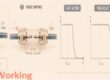
The outputs of the SP3485 driver are differential outputs compatible to RS-485 and RS-422 standards. Typical
the no-load output voltage swing will be 0 volts to 3.3 volts.
With a 54Ω load across the differential, outputs are drivers
can maintain a voltage level higher than 1.5V.
The SP3485 driver has a control line to enable the driver which is active HIGH. A logic HIGH on DE (pin 3) is activated differential controller outputs. Logic LOW on DE (pin 3) three-state controller outputs.
The SP3485 driver works up to 10 Mbps. The maximum limit of 250 mA ISC on the output of the controller allows
SP3485 to withstand an infinite short across -7.0V into the 12V normal mode range without serious damage
to the IC.
SP3485 receiver
The SP3485 comes with differential inputs with an input sensitivity of ±200mV. The receiver input impedance
is at least 12 kΩ. Wide common mode range from -7V to 12V is used for large ground potential differences between systems. The receiver consists of a fail-safe function which guarantees that the receiver output will be in the HIGH state when the input is left open. Receiver The SP3485 operates at up to 10 Mbps
The recipient of this model has enabled a control line that is actively low. Logic low high on RE will enable differential receiver. A logic HIGH on RE (pin 2) of the theSP3485 will disable the receiver.
Low Power Shutdown Mode
Low power shutdown mode is started by specifying both RE high and DE low. When the device is turned off usually draws only 50 nA of supply current. RE and DE can be driven simultaneously; the part is guaranteed not to enter shutdown if RE is high and DE is low for less than 50 ns. If inputs are in this state for at least 600ns, parts are guaranteed to shut down
Allow times for tPRZH, tPZH, tPRZL, and tPZL to take over the part was not in a low power shutdown state. Enable tPRSH times, tPSH, tPRSL, and tPSL to assume that parts have been turned off. It activation of controllers and receivers takes longer low power shutdown mode (tPRSH, tPSH, tPRSL, tPSL). from driver/receiver deactivation mode (tPRZH, tPZH, tPRZL, tPZL).
How to Use SP3485
SP3485’s driver output is a differential output that supports RS-485 and RS-422 standards. For no load output voltage varies from zero to +3.3 volts. The drivers maintain a higher than 1.5 volts level with a load of 54 about differential outputs.
The driver of SP3485 comes with a high active HIGH driver enable control line. the differential driver output is enabled with logic HIGH on DE PIN 3. Driver output will be tri-defines for DE (pin 3) is logic LOW.
This driver also supported 10Mbps. The SP3485 faces a higher short circuit with a -7.0V to +12V common-mode range without affecting due to the 250mA ISC maximum limit on the driver output.
The differential inputs of the SP3485 receiver come with 200 input sensitivity. The input impedance is about 15k (12k minimum).
The higher ground potential difference between systems is due to a larger common mode range of -7V to +12V.
Input is unconnected receiver comes with a fail-safe function that makes sure receiver output has HIGH state.
The receiver of SP3485 has features to handle 10Mbps of data.
Receiver features enable a controlled line that is active low. The differential receiver is enabled with logic low on RE (pin 2).
Applications
- It used for industrial communication system
- Used in automobiles
- The multi-node communication system has this module
That is all about the Introduction to SP3485 all details have been explained. If you have any questions ask them here