 Hello, guys welcome to new post. We will discuss Introduction to SG3524. The SG3524 is an integrated circuit that comes with different functions such as power supply regulation, and inverter. It is used as a control module in different high-power devices.
In this post, we will discuss different parameters of SG3524 pinout features and applications. So let’s get started Introduction to SG3524.
Introduction to SG3524
- The SG2524 is an integrated circuit that is used in different applications like regulating power supply inverter circuit and switching regulators.
- It is created for any type of polarity transformer coupled dc to dc converter, voltage doubler circuit having not transformer.
- It is also used for circuits where polarity change is needed with frequency fixing and the PWM technique
- Its complementary output needs single and push-pull circuits.
- This module comes with a regulator, amplifiers for error, pulse string flip flop, and oscillator.
- It also has 2 no committed pass transistors, a comparator of high gain value.

SG3524 Features
- The main features of this component are discussed here
- It comes in packaging of PDIP, SOIC and PDSO with sixteen pins
- Its rise time is 200 ns and fall time is 100 ns
- Its maximum duty cycle is forty-five percent
- The value of switching frequency is seven twenty tow kilohertz
- Its main topology are Push-pull, fly back, boost and forward
- It has 2 outputs
- The value of output current is fifty milliamperes
- Output volts are 4.6 to 5.4 volts
- Input volts are eight to forty volts can give
SG3524 Pinout
- Its pinout are explained here
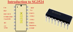
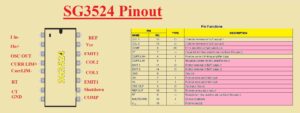
- Pin 1 is IN- that is inverting input to error amplifier first
- Pin 2 is the non-inverting input to first amplifier
- Pin 3 is the output of an oscillator
- Pin 4 is used for positive current limiting amplifier input
- Pin 5 is the negative current limiting amplifier input
- Pin 6 it is resistant for adjustment of oscillator frequency
- Pin 7 is the capacitor point for adjustment of oscillator frequency
- Pin 8 is ground
- Pin 9 used for error amplifier compensation
- Pin 10 was used for shutdown the component
- Pin 11 is the emitter pin of BJT first output
- Pin 12 is the collector pin of BJT first output
- Pin 13 is BJT second output of collector pin
- Pin 14 is the emitter pin of BJT output
- Pin 15 is the input supply
- Pin 16 is a reference

SG3524 Absolute Maximum Ratings

SG3524 Applications
- It used in circuits of solar power inverters
- Used in the smoke detector
- Used for ac and dc power supply
- Used in E-bikes
- Used in washing machines
- Micro inverter based on solar used this module
- Used in PSCu server
- Used in computer
That is all about the SG3524 all details have been explained if you have any questions ask in comments. Thanks for reading have nice day


